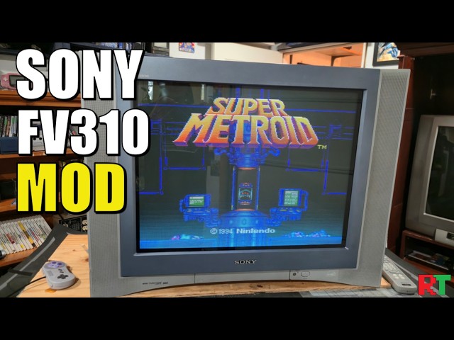
Video summary
The video documents the comprehensive restoration and RGB modification of a Sony KV-27FV310, often referred to as the "grail of all grails" among CRT enthusiasts. The television was rescued from a landfill after its rear casing was destroyed, though the screen remained pristine with no scratches. To complete the chassis, a replacement back shell sourced from a similar FS320 model was installed, along with a new bezel that fit perfectly. Before tackling the RGB conversion, the host spent approximately twelve hours performing an extensive internal restoration, which included replacing 63 electrolytic capacitors across five circuit boards, reflowing solder joints, and reseating loose yoke wedges using silicone adhesive to ensure stability.
The core of the project involved installing a Sector Syntar RGB mux kit to convert the analog inputs into a digital RGB signal. This process required removing specific resistors and jumpers on the A-board and carefully installing diodes with custom-bent leads to manage signal flow for red, green, and blue channels. The host also routed audio connections and sync signals, initially deviating from the standard guide to route cables more cleanly along the bottom of the board. A significant troubleshooting hurdle arose when the TV failed to power on correctly; the issue was resolved by inserting a dummy S-video plug into the input port, which is necessary for older kits of this type to activate the SCART functionality properly.
Once reassembled and powered up, the television demonstrated exceptional performance with vibrant colors, accurate white balance, and no blooming effects during high-contrast scenes like the opening sequence of *Teenage Mutant Ninja Turtles: Turtles in Time*. This lack of blooming is attributed to the FV310's unique dual flyback design and voltage regulation circuitry, which effectively handles rapid voltage changes that typically cause image expansion on other CRTs. The host successfully tested various consoles including the Sega Dreamcast, PlayStation 2, and even light guns, confirming that the modification preserved all original features while adding modern digital capabilities. Despite the slim profile of the screen making corner convergence slightly challenging, the overall result was a glowing tribute to high-end CRT technology that lives up to its legendary reputation.
Read the full video transcript
[music]
>> Hey guys, welcome back. Today we are
looking [music] at a Sony KV uh it's a
the grail of all grails
the FV310. This one is a 27-in and
and it's come to the shop first to be
restored and then ultimately to be RGB
modded with um
the Sector Syntar RGB mux kit. So,
that's what we're going to do today. I'm
going to briefly show you uh an overview
overview of the internal hardware first
and then I'm going to jump in and we're
going to go really detailed into the RGB
mod and I'll even show you the trouble I
ran into and all the troubleshooting I
had to do. Uh before we get into that,
please remember to subscribe to the
channel if you like CRT content and CRT
related stuff. And um
that's pretty much it. So, let's just
jump right in and check out this Sony KV
FV310.
And we're going to take our first look
at the Sony uh FV310.
And this is the KV27,
so 27-in flat
flat Vega Trinitron tube here.
And
pretty iconic front bezel and look to
this TV.
And I've already removed the shell.
The interesting story on this one is
it was sent to the dump
and
was rescued
after it either arrived at the dump or
when it was thrown out to go to the
dump, but
the owner told me the back end of the TV
was completely destroyed,
meaning the back shell.
And then
here we have a pretty bad impact point
on this piece of plastic on the bezel,
but thankfully there's nothing in this
entire corner
um that would be damaged by that
impact. So, there was no
damage to the actual TV itself. The
screen doesn't even have a scratch on
it. And
so, we finally get to see the FV-310.
And if we look over here, we do have
a label
telling the information on this
actual TV and that it's a 310, December
of 2003.
Now, the owner was able to source a
replacement back shell
from a FS320
from roughly the same time period. You
can see over here he took the label from
the broken
back
of the original and taped it.
Um but here's the replacement back
shell. So, if you find
yourself needing
shell parts, it's probably a good chance
that
any of the parts from the 320 will fit
the 310.
Uh
not the actual hardware inside as far as
certain things, but other things like
the shell and maybe even the bezel will
fit.
And over here we have the subwoofer
with this cool speaker design, right?
Over here, I loved how Sony, you know,
they got quite inventive inside these
CRTs
um
to try to enhance sound performance.
And then over here we've got our
Sony uh
10 ohm 5 watt speakers.
So, stereo audio on this TV set.
There's a lot of extra hardware inside
of here. You've actually got a second
board
on these later high-end
Sony
>> [sighs]
>> uh TVs that
would do extra functionality to try to
help you with your picture quality
basically. Uh but here's our standard
socket board, neck board if you want to
call it at that. This is the flyback
transformer.
And then this board, the D board
is mostly power, looks like.
Yeah, we've got even power stuff in the
audio power, it looks like right over
there. You see that marking on the board
where it says audio for the woofer.
And you got some big caps under there.
So, that's not really the caps I'm
worried about on this one. We're more
worried more worried about just getting
the uh
deflection capacitors
checked out and replaced.
And then um
also the power capacitors
that are kind of over here jumbled up.
We're going to replace those because
that's really one of the higher heat,
higher uh voltage areas.
This is where your power comes in
directly from the wall.
And then uh that is our power supply for
the most part.
Spent about 12 hours working inside the
CRT here.
And I have
restored
pretty much every board uh to some
level.
And most of it is caps being replaced as
well as uh
solder being reflowed and inspected
on all these boards inside here.
And
a total of 63 electrolytic capacitors
were replaced.
And that's on a combination of all
these. I mean, there's like five circuit
boards in here.
And uh it's not every single capacitor.
There's probably twice that many
actually in the whole CRT.
And then I went ahead and re-seated
these yoke wedges cuz they had all come
loose.
And what I've used there is just some
black RTV silicone. You see that around
whoop around the wedges right there?
And that will hold those and they'll
pretty much never move now unless
someone were to come in here and
intentionally uh
peel that off the back of the tube and
try to move it purposefully. So, that's
good. And actually, what we're going to
do next is tear it down again, not
completely, but we're going to remove
this
um board right here, the A board, and
we're going to install this Sunthar's
RGB mux kit.
Uh that's pre-prepped.
So, I'll link in the description uh more
information about this specific mod.
We're on our A board here and we're
going to remove three resistors to start
this process.
R2020
022
024
and
I'm just going to do this with my
soldering iron.
It's pretty simple.
There we go.
Just like that.
I'm actually going to
clean these up.
Some solder wick.
I just want to avoid R19 and R21.
Everything else
is not populated.
>> All right, let's see how
we look here.
Everything looks pretty good.
Ready to move on to the next step.
Next step, I'm going to remove some
jumpers.
There are three of them here.
And they're not labeled on this side,
but on the other side is jumper wire 42,
43, and 44.
So, I'll show you a picture of the other
side, but I'm just using my desoldering
iron or tool here, the FR-301.
And I have put fresh solder on each of
these
points.
Just to make it easier.
Let's see if we got all the solder out
there. If so,
our jumper
wires will just fall right out
through here.
Yeah, it like we did pretty good.
So, that's it. Those three jumpers need
to come and uh oops, be removed.
Goodness gracious. Okay.
>> [snorts]
>> That one
may still need a little solder removal.
Okay, there we go.
All right, so this is a jumper.
And uh we just need to remove this one.
All three of these right here.
And then we're going to install some
diodes in their place. Okay, I'm trying
an interesting technique here. This is
my diode
and it's flowing towards the left side
over here towards this little hook.
Um
so that's the way the diode flows. So,
if we look over here where we're going
to be installing it
down
um in the jump jumper wire section, you
notice my board has a connector there
that a different board will go into.
Uh right here.
Right in here, a whole board sits going
to go in there.
So, what I've done is I've set the diode
to flow again away from this chip right
here
and towards the connector and the
capacitors. That's the direction it
needs to flow, but I've installed that
hook so I can come in and
um do a cleaner job of installing the
conductor wires than what we've got up
here on our demonstration.
And uh I just
want to try to make it a little bit
simpler on myself. So, I'm going to
I'm going to do a slight hook on that
diode
uh lead right there that I've just
custom bent.
And I'll show you
how this looks when I get it
three of them installed right there.
Okay, and here is what I'm talking about
on the
diodes.
Now,
each of them has a little hook
on the end, and that's where I'll attach
a conductor with the red,
blue, and then the green closest to that
burgundy connector over there.
And
I may even be able to get a nice
heat shrink tube to fit over
those points
and make it look real professional with
the hooks.
All right, guys. I'm about to install my
conductors. I'm going by the guide again
at Sunthar for this chassis, but I'm
going to make some alterations to my
design and my installation. There's the
hooks on that side for our
red, green, blue.
And it says I can get
3 V for blanking right here from this
jumper on the other side.
And so, you can see I've already removed
that jumper, and I installed a new
jumper that I had put a hook on, so
that's where four of the conductors from
our RGB mux kit will go.
And then up here is where we're going to
connect for sync.
And
um according to the guide, they went
with the S-video connector up here,
which
gets in sync on luma.
Um
but I'm going to actually connect down,
cuz if you see, you can see there's a
trail leading down there. I'm going to
try to maybe connect down here
for sync and then ground just to make it
look cleaner,
and I can run the cabling
kind of closer together down there.
We'll see. Uh but that's where those
needs to be those need to be connected.
And then I'm certain that there's going
to be an audio connection. All right,
I've installed all the conductors and
let's just start on the bottom side
here. You've got my
left and right audio
connected over here
to the two points that are on the
board marked
for left and right audio and then
I used this point for the audio ground
and I fed it around up top. I couldn't
actually find a way to get
to those connectors right there for the
left and right audio from the top side
but that right there is I know it looks
white but it just has a little piece of
the white shielding left on it.
That's a ground cable, the black cable.
Purple is also ground cable and I've yet
to clean these points so they are a
little dirty but um still has some flux
on there so I'll I'll brush all that
off. So there's the yellow conductor.
That's sync. Go down here some more.
There's our installed red, green and
blue
with
heat shrink tubing. Same thing over here
with the blanking.
Heat shrink tubing. Looks great.
And then right there is another ground,
the brown wire. So you have brown,
purple and black, three different
grounds. They all connect on the same
ground loop within the CRT.
So let's get this all reassembled and
see if we did it correctly.
All right, so I was doing some quality
control checks and I always recommend
you do that especially when you're
working on something like a
modification.
Uh everything's right over there, red,
blue, green.
I had these wires swapped so that's a
good thing I didn't just go and try and
test it.
Uh the brown wire is supposed to be
the blanking signal or the five uh 3
volts actually.
And then over here is just the ground
and
I went up to Suntar's guide for the
cable and the coloring on the cable. And
that tells you everything you need to
know.
Okay, TV's back together and powered on.
Let's see what happens when we turn on
our C-syncs console RGB.
Oh.
Okay.
No, no, no, no, no. That is not right at
all.
All right. Um
Wow. Yeah, definitely not correct.
Well, I managed to figure out the issue
with the RGB mod. I've
I've got the kit taken off here cuz I
was fitting it to the outside shell.
But what was happening is I forgot that
this older kit and this particular TV,
it's syncs fed in through this S-video.
So, you have to put a dummy plug in it
to get it to work. So, I had to put a
just a S-video cable from the N64 into
it. I didn't have to put any signal and
then it just came right on.
So, that's a good thing.
Uh everything in here has been finished
up on touch-up. Um
I did install one convergence strip
strip over here to help correct that
corner convergence. I've gone through
all the geometry.
I also had to move these two rings.
Uh these two front rings up here control
the screen bow at the top and the bottom
of the screen here. So, if it's a little
bit bowed out, you can
tilt those rings just a tiny amount. You
could see how far I had to end up moving
it. I had to move this one about oh, I'd
say an eighth of an inch.
Um
to correct the tilt and everything. So,
this thing's ready to go. I'm going to
uh get the back closed up here. Let me
show you what that looks like. I did
install this SCART back here. It looks
pretty good.
And um now I'm going to try to fit this
on the back of the television
without breaking anything else and
hopefully I can get it plugged up
and SCART will work.
All right, here it is put back together.
Got the dummy plug in.
Got the
SCART plug in
and then you can hear
Super Mario World. You're going to get
that more A pattern and a bunch of
strobes because
this is not the greatest
screen to try to show you, but I just
wanted to show you that it is working.
Let me
turn the volume down. The OSD works.
But again, you have to have the dummy
plug in
for this particular build out. Now,
somebody did tell me that there may be a
new board from Sunthar that
adds a transistor that doesn't have to
have
the dummy plug, but the dummy plug
really isn't a big deal. You could
leave the N64 plugged in and then use it
when you want or some other S-video
device.
Just switch back and forth between them.
Looks pretty good though.
Um, I've done
Today I'm using my physical copy of the
240p test suite on the Sega Dreamcast
running currently at 240p
scroll pattern through RGB.
And I'm just going to run through some
test patterns real quickly and show you
the quality of this screen after
adjustment.
Okay, under test patterns
I'm just going to go to geometry to
start off and we're going to look at the
monoscope pattern that's provided here
within
this
disc.
It's a little bit different than the
newest version, but overall it looks
pretty good. There is a little bit of a
horizontal shift which you'll see
between every single console that you
use analog video with.
And even the Sega Dreamcast.
There.
is
um
not a whole lot of like issues on the
screen. I mean, everything looks really
fantastic for the most part.
In the corners, you're still going to
have a little bit of convergence
uh separation down here at the very
bottom line.
It's just too difficult to get any kind
of magnet
in there.
And uh
if we zoom in to the very bottom
corners, you'll see it blow out a little
bit. It's not nearly that bad when you
go in about a quarter of an inch, but
really the flat screen technology on
CRTs always struggled a bit um with
convergence beam alignment in the
corners.
And also, this TV is quite slim. I mean,
it's not the slimmest CRT in the 27-in
size, but it is very slim compared to
something like a JVC D-series.
And uh so, that definitely helps
contribute to that.
And it doesn't show up perfectly on here
because
there's some glare and um more A
patterns on the screen, but this really
does have nice balanced color. The white
balance is great.
Again, through RGB, just looks
wonderful.
One thing I wanted to test was light
guns. I always get the question about
light guns and RGB mods, and the light
gun has no [music] problem working
through this TV. I'll go through how I
had to set it up. Uh but, this is RGB,
and I'm using a light gun here through
the PlayStation 2, and it works
perfectly.
>> I have my light gun in my PlayStation
Slim.
That's what you just saw me using. And
then it comes through and it has this
composite hookup for the light gun
itself. And then I'm guessing this is a
very old SCART cable, but I'm guessing
it must be C sync cuz everything I've
had to get uh
had to use with this TV so far has
needed to be C sync. But there it is
going straight into SCART
uh out of the console.
And uh this isn't part of it.
That was just a different cable.
Uh it does need the dummy plug
to activate the SCART input on this TV,
but that's really the only weird thing
about it. Everything else, I mean, this
thing is gloriously awesome. All right,
guys. This was a really fun project to
finally get to tackle. I've been waiting
years really to not only have a nice
FV310 here in the shop, but uh
also have an opportunity to modify it
with RGB.
This was again the first FV310 I've had
an opportunity to even use myself. The
FV310 does have a lot of hype around it.
People are always talking about how
great it is, but this is one of those
few TVs that personally I believe lives
up to the hype. And the major reason is
because of that
dual flyback or a
There's like a output resistor something
like going on here where you've got
um
voltage regulation uh that's not on the
other Sonys that you know, it it
eliminates the blooming effect. And I'm
sorry if I just like scrambled through
all that and didn't really talk about it
in the most technical terms, but in the
most part when you're using a CRT like
this um generally speaking and you have
flashes of white on the screen, it'll
cause your image to expand in size and
bloom. And that's because the old CRTs
had a very hard time of regulating that
high change in voltage from a black
screen, which is nothing being
transmitted onto the tube, to all of a
sudden a big white screen. So, if you
flash a lot, uh you'll notice this a lot
like Teenage Mutant Ninja Turtles
opening for um
Turtles in Time, how it flashes before
the turtles come down the screen on the
opening title sequence. That's a good
test to show this. But, the FV310
actually has an engineered process to
get rid of that. I also really like
these subwoofer in the sound system on
this TV. It does everything you want as
far as like um
composite, S-video, component, and now
RGB with this kit installed. I was able
to run through every console that does
analog video, and I just had a great
time using it. Um especially now getting
to use the RGB input. The big trouble I
had, obviously, was I didn't realize I
needed that dummy plug in. I should have
thought about that and like researched
the whole mod more, and I maybe would
have remembered this.
But, I did not. So, I spent like hours,
I'm telling you, after you saw where it
wasn't working, trying to figure out
what I'd done wrong. I thought I had
installed something wrong on my process
of installing it, and maybe my
conductors were
connected incorrectly, but all that was
actually bogus. It was literally the
problem was I'd forgotten to plug in
that dummy plug. So, definitely do that,
and you won't have any trouble.
Um
I was able to use like a Dreamcast
with 480i and 240p looked awesome. And I
tested out the Genesis, I tested out the
Super Famicom, and uh really, again,
anything that I could find that I threw
at this thing, it looked awesome. And
you're getting basically all the
benefits from the CRT, you're getting
now RGB input, and you have an extra
large screen, great sound system. uh
These TVs will support an awesome remote
control. They have really good like
features in their menu. And so that
yeah, this was a great experience for
me. I know the owner of the TV was
really happy. It was a ton of work.
Ton of work. I mean, we had to replace
over 60 capacitors inside and work on
many boards. A lot of adjustment phase
had to be done.
And finally the RGB mod. So this is
definitely something I think that
people should only do if they're really
really experienced
in doing this level of mod work.
Personally, I love doing this stuff, and
this is the thing I do every day here in
my shop. So if this is something you're
considering doing, you can reach out to
me through the links in the description
to get in touch with me. The only people
I really do work for is Patreon members
at this point. So you can go through and
go to my Patreon account, sign up there,
and you can get into our service queue
if you want to have a professional
service job like this done to your Sony
KV- FV310.
Thanks again everybody for watching this
long video. I really had a great
experience again with this TV. If you
enjoyed this video, remember to hit the
like button um down below. It will help
out with the algorithm, and it will help
out for other people who are interested
in seeing this CRT job get done. It will
help the reach of the video a little
bit. So that's all I ask for you is to
do that, and have yourself a wonderful
day. I'll see you guys next time with
some more retro content.