Tatev Margaryan | FPGA-based Audio Processing System Implementing Convolution Reverb
Watch on YouTubeVideo summary
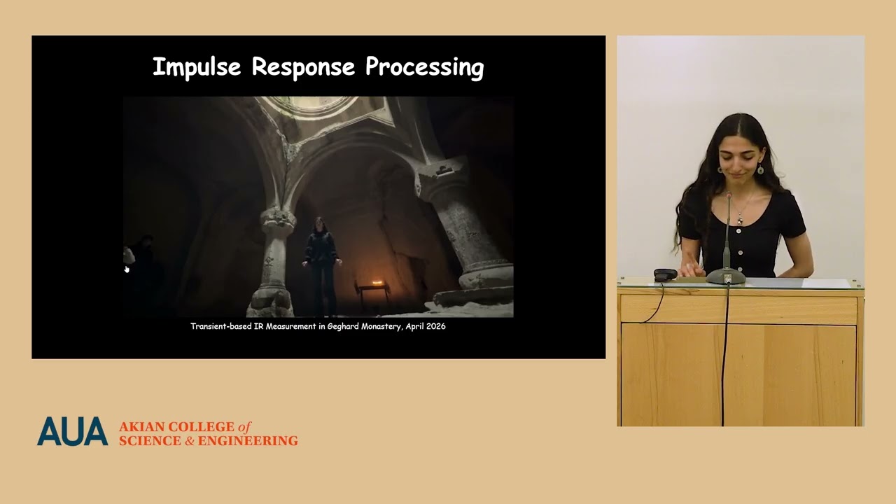
The video presents a capstone project focused on developing an FPGA-based audio processing system designed to implement convolution reverb, allowing musicians to experience specific acoustic spaces through their instruments. The creator's journey began with field research in Armenia under the Heritage Acoustics initiative, where impulse response measurements were conducted at culturally significant sites like monasteries and churches using a microphone-speaker setup. This data was published on "Armenia Sounds" for public access, but the core motivation evolved into creating a standalone device that could integrate this acoustic data directly into musical settings via effect pedals. The ultimate goal was to build hardware capable of giving music the perceptual character of these unique spaces without requiring complex external setups during performance.
To achieve real-time processing within resource-constrained FPGA environments, the project relied on three fundamental digital signal processing concepts: convolution, FFT-based frequency domain multiplication, and the overlap-add method. Standard time-domain convolution was deemed too computationally expensive for live audio, so the system utilized the theorem that convolution in the time domain is equivalent to multiplication in the frequency domain by employing Fast Fourier Transforms (FFT). Since real-time audio streams continuously, the implementation used the overlap-add technique to divide incoming sound into manageable segments; these were processed individually and then recombined with overlapping tails to ensure a seamless, undistorted output. This approach allowed for efficient computation while maintaining high fidelity in the reverberant effect.
The hardware architecture was built around Microchip's PolarFire SoC Cyclone kit paired with an WM8731 audio codec responsible for analog-to-digital and digital-to-analog conversion via I2S interfaces. The FPGA design featured a custom DSP core managed by several specialized blocks, including ping-pong buffers to handle data flow conflicts between the continuous stream from the codec and frame-based FFT processing, as well as managers for multiplication and output reconstruction. A critical engineering challenge involved balancing acoustic richness with limited silicon resources; through extensive Simulink simulations, the creator determined that using 8,192 samples of the impulse response was the optimal "sweet spot" to eliminate perceptible latency while still capturing enough of the long decay tails found in spaces like the Gavit Monastery.
Validation of the system's effectiveness was achieved by recording musical pieces performed by a choir both inside the monastery and in an acoustically dry studio environment, using the latter as a reference for applying digital reverb effects. The final presentation demonstrated that the FPGA device successfully reproduced the immersive acoustic character of the original space with minimal latency when connected to line inputs or guitars. While future iterations plan to add controls like wet/dry mix balancing and support for multiple locations via partitioned convolution techniques, this project stands as a successful integration of physics-based acoustics and hardware engineering, creating a portable tool that brings the unique soundscapes of Armenian heritage sites directly into modern musical performance.
Read the full video transcript
[music]
Hi everyone, I am DV and the next 20
minutes you'll be hearing about my
capstone project. The title is FBJ based
audio processing system implementing
convolution reverb.
My project starts with a backstory. Last
year I uh with together with other AOS
students was a part of heritage
acoustics re research in Armenia
initiated by an acoustical engineer from
New York Ethan Bordeaux. And as a part
of this research we would go to
different culturally significant
Armenian sites such as monasteries and
churches and then we would complete
acoustical measurements. Here you can
see uh which exact uh sites we visited
both last year and this year.
What were we doing there? So using a
very straightforward setup consistent
from a microphone and a speaker. We were
doing uh acoustical measurements or
impulse response measurements. So the
speaker would generate a signal or the
impulse and the system which is the
let's say the monastery uh would um
respond to the signal and the microphone
would capture the both the direct sound
and also the reverberation the
reverberant tail. On the right side
picture you can see the hedgehog plots
that the software spits out.
So as you can see in the plot the very
center is the location where the
microphone was placed and all the other
vectors show where the sound arrived
from. So as the color goes more towards
blue it means that the color was uh has
arrived later. [snorts]
So you can understand how reverberant
the spaces were. After uh we did this
experiments, we would um of course a
paper was published and also this
analytical data was placed in a web page
Armenia sounds. So it is available there
and everyone who wants can access it and
use it later for different purposes. So
that was my that that was the question
that arised uh how to actually use this
data, how to integrate it in different
uh applications and then came this idea
that this acoustical data can actually
be used in musical settings. So uh I'm
sure you're aware of uh things like
effect pedals. So uh when musicians are
connecting their instruments to these
pedals playing and these pedals uh shape
the sound give a more character to sound
in different ways. So the idea was to
incorporate this data into a device
standalone device that would give the
perception of a space to the music.
Then um to actually implement this
device I had to follow different very
crucial
uh digital signal processing concepts.
And the first one arguably the most
fundamental uh concept in DSP the
convolution. It is about taking those
two signals and performing this
operation the sum on them and as a
result
getting the third signal that
incorporates some information about
those first two inputs. So in my in
sense of my system uh this two signals
inputs should have been the real-time
audio or the music and the second one
should have been the impulse response of
the space. uh this is very good
straightforward. However, it has a big
issue. So to do this operation, it is
very uh processing expensive. So in
other words, it uh needs to compute a
lot of uh things and uh it is not very
effective. It uh requires a lot of time.
That's why I had to follow um I had to
look for better alternatives and I found
this other flavor of convolution which
is called FFT convolution. Um the
theorem goes that convolution in time
domain is the same as multiplication in
frequency domain. So in other words,
wait, in other words, if I took the
impulse response and the audio signal,
converted them to frequency domain using
fast for transform, got the real and
imaginary components, then multiplied
simply multiplied those together, got
the result, and then converted the
result back to time domain using inverse
FFT. I would be left with the music that
sounds very reverberant and encaptures
the acoustical character of a space.
And the last very crucial concept that I
had to implement is overlap add method.
So since I am dealing with real-time
audio and it's continuously coming, I
need I cannot um I cannot u
simultaneously process the whole thing.
So I have to divide it into segments.
Then I had to process the segments
separately and later I had to combine
the overlapping parts. For example,
let's say the first frame uh goes from
uh samples 0 to 200. Then the second
frame goes from 100 to 300. Then the
overlapping part the tail of the first
frame and the head of the second frame
had to be combined together. So this
ensures that audio is continuous. It
does not distort or it does not have um
cuts.
So these were the uh theoretical
background of my project. And here comes
the hardware setup. I decided to use an
FPJ based platform. More specifically
the PolarFire SOC icycle kit from
Microchip. Uh the reason to use FBJ is
that it allows to have dedicated
pipeline and continuously process the
audio and also and also it allows to
have very deterministic low latency.
Together with icicle kit I had to use an
audio codec. It is called WM8731
very unique name and uh the it had two
very important responsibilities. First
one is the analog to digital and digital
to analog conversion. As we know the
real world signals are analog. However,
my FBJ is purely digital. It understands
only digital. That's why we need this um
codec to take care of that conversion.
And besides that conversion, this codec
is also responsible for packaging the
digitiz digitized data into uh interface
acceptable for later processing which is
I2S interic sound. And one important
point here is that this audio codec
required to be configured using I2C
commands that I uh sent from my FPJ
board. Here comes the system
architecture. You can see that line
input is the input of my system. It
passes through the audio codec gets
digitized then enters the FBGA. Later
the I2S receiver side accepts it and my
DSP core starts. I will talk in more
detail about all the blocks I have
created inside the DSP. So this is the
uh highle overview. So later as the
signal gets processed it goes out of the
DSP core enters the I2S transmitter site
and out of it goes to the audio codec
once again and later uh gets an uh
becomes analog signal.
Before starting the FPGA design I had to
actually prove that this DSP concepts
are operating correctly. So I did um
Simolink model simulation uh using um
DSP libraries provided in Simolink. I
created this model that implements all
the theory that I was describing just
before. And the most important um
advantage that this model gave is to
very easily understand how different
impulse responses affect the result. So
more about it here. So to start with the
to start processing the impulse response
firstly we have to measure it and here
is how it happens. So um this is going
to be loud so please don't be afraid.
It has a long reverberation tail. So
that's why it lasts very long. So um
inside this monastery which is Gart
monastery I had to use transientbased
impulse response approach which means
that I had to give the space very short
wideband signal which in this case was
the balloon pop and I had to record this
balloon pop and inside that recording I
would have not only the direct sound but
also all the reverberation that comes
after the direct sound. In the left
picture you can see the specttogram and
what is interesting about it is this
very long um bright line on the lower
part which means that the low
frequencies take very very long to decay
completely. A fun fact is that in one of
the rooms in Gard complex this value was
around 22 seconds. It's very large. Uh
and uh after this measurement, our team
was seriously considering for applying
to Guinness records to register this
value. Um after I get this recording,
this is just a wave format audio file. I
give it to MTL to find the FFT or the
frequency spectrum of it. On the right
picture, you see the impulse response on
the upper part and the uh corresponding
frequency spectrum. So one important
thing is that this impulse response is
very long. However, my resources in the
FBJ are limited. So I cannot put the
whole impulse response into the FBJ. So
this is a trade-off point which I had to
consider. So if I take many samples from
impulse response, my output will be very
rich in reverberation. However, my
resource utilization will be very bad.
And on the other hand, if I cut off the
number of uh samples from the impulse
response, the effect won't be very good,
but it will be good in terms of
utilization. So uh actually Simolink was
the having Simink model was to was to
experimentally test which is the good
spot to have both good effect and uh
acceptable um resource utilization. So
this was a point where technical and
artistical uh approaches should be
balanced.
Then after I have tested everything and
proved the theory, understood how many
samples I should take from the impulse
response, then came the FPJ design part.
This is the top view. The whole design
that I had this um rectangle, this sub
hierarchy we call it is the main DSP
part. Everything outside of it is
responsible for um talking to the audio
codec and configuring it. One important
point I have to mention is that in here
you notice both gray and blue blocks. So
this blue blocks are provided IP cores
meaning they are similar to Simolink
libraries. So things such as uh FFT or
complex multiplication those are just
provided. I did not uh design them from
scratch. But instead these gray blocks
you see are custom made. So I designed
them using vlog and those are
responsible for managing the data
movement and in more detail I will talk
about them now. First I have the checkin
manager with the highlighted nets. You
can see what it is interfacing with. So
the reason to have this uh check-in
manager is the uh conflict we have in
here. So the audio codec continuously
delivers audio samples. It does not um
look for what else is happening later in
the chain. However, my FFT block needs
to have frames, not samples. So in other
words, it has to have certain amount of
samples before it can start processing.
And whenever it starts processing, it
stops accepting any new samples. Meaning
that if I did not have this proper
handling, I would lose samples and audio
would be just simply distorted and I
will lose data. That's why I use this
thing called pingpong buffering. So it
is uh about having two placeholders.
These pingpong buffers are just ROM
blocks. And whenever let's say the pink
buffer is getting filled it reaches the
certain amount the maximum amount then
this frame is transferred to the FFT and
while the FFT is starting cooking
processing the frame the other block the
pawn buffer starts filling. So this
ensures that no data is lost.
Then comes the main manager of the
system the malt manager or
multiplication manager. [snorts] So it
is responsible for taking the impulse
response frequency beams from the rams
that you can see on the upper part, the
impulse response imaginary and real
blocks and also take the uh the blocks
um the samples from the FFT and um it
has to make sure that correct samples
are multiplied together. So the correct
frequency bins are being multiplied and
after the multiplication it transfers
the samples the result to the inverse
FFT block which converts this result to
time domain
and the
after that I have the output
reconstruction stage which is managed by
overlap ad manager as I mentioned before
it is responsible for delaying the tail
part of the arriving frames and adding
them to the head part of the next frame.
And the very last design point is the
check out manager. So after the whole
processing happened, I need to send the
samples out of the DSP core. So check
out manager is quite the opposite as the
checkin manager. So it has the frame to
stream conversion responsibility. So my
whole DSP chain produces bursts of
stream uh bursts of samples but my later
chain should accept continuously. So
this checkout manager simply accepts the
burst takes uh puts it in a circular
buffer then contin continuously reads
from this buffer.
that much about my FPJ design. And all
of these things are inside this little
chip, a piece of silicone which is the
FPJ chip. And um in this picture you can
see the enclosure which contains all of
this together the icicle kit together
with the audio codec. And
on this enclosure, you can see the power
supply opening, the micro USB openings
that are meant to deliver or the flash
the bitstrm into the kit. And of course,
you can see the audio connectors that
are meant to connect the line input and
output.
And now comes my favorite part of this
presentation, which is about design
validation. So how did I know whether my
design um acts good? How I am sure that
it convolves the input audio correctly?
So to check that I took advantage of the
fact that I sing in a choir and I
invited my choir to come with us during
Gart experiments. And there we um we
recorded several musical pieces which
was the the the golden reference the way
that my system should convolve the
incoming audio. And besides this golden
reference, we also recorded the same
musical pieces in a studio session where
there is no reverberation. It's a dry
acoustical environment. And later I used
this dry recording, applied my effect on
top of it and checked how similar it
sounds to the actual recording. And now
we finally can hear
>> [music]
>> Now comes the dry recording.
And now the convolved output. Put
something on.
>> [music]
[music]
>> So we can notice that of course there
are differences but the whole
reverberation effect is there. important
point. How did I actually do this
validation in um actual testing? I would
connect my computer to the uh line input
connector of my box. Then I would also
connect my headphones to it and I would
see the effect being applied real time.
However, to share it with you as well, I
instead of headphones, I connected
simple recorder to be able to also put
this in my presentation. One more thing
I uh I did not mention is um the design
or the enclosure [snorts] and also I
should thank Tanik Danalan for helping
to cut this enclosure and as u effect
pedals uh different effect pedals have
names I decided to name it arzag which
means uh eco in Armenian. [snorts]
Uh yeah
and about future work uh as for now it
only has the impulse response of Gart
monastery. However, it would be great to
have not only Gart but other places as
well and to be able to select select
which which um space you want to be in
and to hear the music from that space.
Second point is that right now it does
not really have any control. um it
cannot uh choose how much uh wet and dry
mix you can hear or the choose the
bypass mode. However, all of that can be
added to uh the design in later stages.
And also one important point about the
longer reverberation tail. So for now I
chose from the whole reverberation a
very long reverberation I took very very
small tiny piece because I was
constrained by FPJ resources and uh
improvement would be to use other DSP
techniques such as partitioned
convolution to make sure that the whole
reverberation tail is included and can
be reproduced using during musical um
performances
that much and I should uh thank I should
um express my appreciation towards these
people. First and foremost, my my
supervisor Guru Jani whose encouragement
um played a crucial role during this
project. I should thank Ethan Bordeaux
whose research in first place was the
reason how I got motivated about this
things and also he helped with the
impulse response measurements and with
the choir recordings. Then I should
thank my professor Miran Gurunan who
advised from the perspective of musical
application and the acqu um artistic
part. Then I should uh mention Dan
Danellang who helped with this enclosure
and also who helped to uh not only test
with the computer but the actual musical
device which was a guitar. So we also
tested that way. Then I should mention
my microchip colleagues who provided
immense guidance with the FPJ design
part. And of course I have to mention uh
my choir design choir our singers and
also our conductor Arus Nazaran who
helped to get the uh recording and also
I have to mention Satan Netakany who
arranged the recording in the studio of
the real school. Thank you everyone for
your help.
Yeah that much. Thank you for listening.
[applause]
On this beautiful note, I will end my
presentation and here for your
questions.
>> Uh I will start.
>> Okay.
>> Um actually having physics in my
background
>> and physics in foreground
>> physics in foreground and um being a
sound engineer in my previous life. Uh I
have an experience recording in some of
these um churches. Oh,
>> and uh fighting against the rever
reverbance in the venues during the
concerts. Um I can say that this is
sick.
>> No, really. I mean,
>> in good sense.
[laughter]
>> I can go with the details on the
questions, but probably I would just
stop there. [laughter]
>> Thank you for your comment.
>> And another question. Have you tried the
delay in the same venues in the same
churches?
>> Delay in what sense?
>> Have you tried to clap?
>> Clap.
>> Yeah. Yeah. Yeah. with um in all the
churches we would do firstly sign sweep
based acoustical experiment which means
that it sweeps all frequencies from low
to high and then we can understand which
frequencies how much they decay and
that's um similar to understanding the
delay how much it takes to completely go
away and only after that we would do the
excitation based uh measurements
>> and the SPS by the way they can have a
very realistic commercial value in some
companies like Stanberg, Yama, Sony and
others who do the digital DSPs for the
digital venue
um reber as a plugins.
>> Mhm.
>> Uh and the controls that you mentioned
for the future some of them are very
easy to
>> Yeah.
>> to do.
>> Yeah.
>> Great work.
>> Thank you.
So I I I can guess that bit is a really
complex and long verb then it the
latency but even if you start
accutulating it the latency is becoming
more and more
>> no
>> that's why [laughter]
[gasps]
>> actually yeah let me go there it was a
very important part because yeah let me
go here I was testing um with different
numbers of impulse response samples. If
I had too many impulse response samples,
I would actually hear the delay. Uh
there would be some time before the
music would actually start playing. But
after that, everything was continuous.
And then I found out that this number,
which is 8,192,
is the sweet spot to have no delay. So
at least I could not uh experience the
delay. At least there was uh no
sounding, no perception of it. And um in
this way um I could keep the impulse
response short enough to not get it.
>> So it is for example
I mean it is not a recording is real
someone talking and you are applying the
rever.
>> Yeah. Mhm.
>> Mhm.
>> Uh yes. So the musical instrument is
connected to it and then I hear the
sound coming already applied with the
effect and there was no delay
>> when you are doing the calculation
sample by sample or prime by prime. So
you are getting deeper. So you have did
all this uh predicts of this river and
you know on which sample out should
continue
>> uh from to where where
>> you mean
>> here. So the the upper let's say the
reverb is taking 22 seconds. Yes.
>> Mhm. and your uh each sample or each
frame is much smaller,
>> right? And then you need to get the the
like you need to take the track where
they in which pump area in the
functional place where your re is
already taken and functioned and which
part need to to
>> Yes. So that's exactly what overlap
adding is about. So whenever you have
some like some frame it is not um
necessarily as long as the reverberation
lasts. So there are parts that are there
are samples single samples that are
getting a reverb from different frames
of process from different processing
stages. So all of that is being combined
in the step of overlap adding
>> and uh during the same sample the reverb
is static.
>> Um what do you mean by that? I think uh
>> the value of the reverb
uh applied on the sample or on the small
period
>> because it is FFT because it is FFT
based. So in in my system I have this
frequency spectrum. So each frequency
has static coefficients. So real part So
real part has the coefficient for
amplitude change and the imaginary part
has the coefficient of phase change. So
these things are static. Every time this
frequency is arriving, it's being
multiplied by the same number. This is
static and prepro processed inside the
FPJ.
>> Thank you. That was very compatible.
[applause]