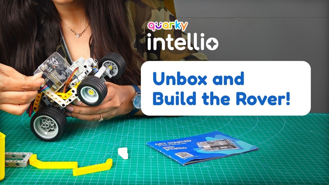
Quarky Intellio Rover Kit | Unboxing and Step-By-Step Robot Assembly | AI and AR DIY Robotics Kit
Watch on YouTubeVideo summary
The video introduces the Quirkbot Intel Rover Kit, a comprehensive DIY robotics set designed to teach artificial intelligence, machine learning, augmented reality, and robotics through hands-on assembly. The kit arrives in two boxes containing a programmable board equipped with a built-in camera, microphone, speaker, RGB LED, tactile switches, and various ports for sensors and expansion. Alongside the main board, the package includes a wide array of construction components such as beams, axles, gears, motors, wheels, and AR markers, all organized to facilitate building multiple projects. The presenter highlights that while many builds are possible, the focus of this session is on assembling the rover, which serves as an excellent entry point for understanding how mechanical parts integrate with electronic control systems.
The assembly process begins with constructing the robot's base by attaching DC motors and bevel gears to the frame using connector pins and axles, ensuring precise alignment for smooth movement. The builder then constructs a servo-controlled steering mechanism, carefully connecting thin beams, cross poles, and L-shaped brackets to create a functional front wheel attachment that can turn left or right. Subsequent steps involve mounting these assemblies onto the main chassis, attaching rear wheels with bush connectors, and securing the entire structure with bent beams and U-shaped frames. Throughout the build, the presenter emphasizes checking connections frequently and ensuring that moving parts like the steering mechanism operate freely before proceeding to the next stage.
Once the mechanical structure is complete, the video transitions to wiring the components, where DC motor wires and servo cables are connected to their respective ports on the Intelio board and expansion board, with careful attention paid to grounding brown wires for safety. The presenter then demonstrates how to pair the robot with a computer using PictoBlox software by setting up a Wi-Fi hotspot on the Intelio board or utilizing Bluetooth connectivity. After establishing a connection, the user loads a pre-coded project that allows control of the rover via keyboard inputs, enabling forward and backward movement, turning, and automatic streaming of video feed from the onboard camera.
The demonstration concludes with advanced features where the rover autonomously navigates based on visual recognition markers, moving forward upon detecting a "go" card, turning when it sees a left-turn marker, and stopping automatically at a stop sign. This integration of computer vision with physical robotics showcases the kit's potential for creating innovative projects beyond simple movement. The video ends by encouraging viewers to explore their creativity with the kit, suggesting that the modular design allows for endless experimentation and learning opportunities in AI and robotics without being limited to just one specific build.
Read the full video transcript
This is Quirkbot Intel Rover.
Hey everyone, this is Avni and today
[music] we are exploring
Quirkbot Intel
Rover kit. It's a hands-on kit for
learning artificial [music]
intelligence, machine learning,
augmented reality, robotics, and so much
more. So, I am really excited to [music]
open this and see what's inside.
Quirkbot Intel Rover kit comes in two
boxes.
>> [snorts]
>> This is your box one.
And that's your box [music] two.
Let me open the box one first. Till
then, I'm keeping box two aside.
So, once you open this, you can see some
course information over here. So, make
sure you refer that. [music]
And so, first up, we have this getting
started booklet.
Then tada, we have our hero product,
Quirkbot Intel. [music]
Now, it's a programmable board with
inbuilt camera, mic, and speaker.
So, [music] on top, you can see two
programmable tactile switches,
RGB LED.
At the bottom, you can see mount for
servo and a SD [music] card slot.
On this side, you can see power
>> [music]
>> on and off switch,
charging port,
and reset switch. [music]
At the back, you can see lithium-ion
rechargeable battery already attached
and [music] some holes to attach
construction parts.
On this side, you [music] can see servo
port and GPIO I2C port over here.
Then in this box,
we have some construction parts
like frame,
pins, and attachment plate.
>> [music]
>> This is USB cable for charging.
At the bottom layer,
we have some recognition markers
and AR [music] markers.
>> [music]
>> Let me keep this box aside.
Now, let's open box two.
Once you open box two, you can see the
entire component list over [music] here
with proper names.
So, first up, we have this
>> [music]
>> pin separator. Can be used in removing
or attaching small components like short
pins,
axles, bush,
or regular pins very easily like this.
Then these are some construction parts
which has different types of
>> [music]
>> beams,
axles,
connectors, pins,
frames
over here.
Then we have this
mini expansion board to connect more
components. [music]
Then we have some wires
for connection.
Two DC motors,
one servo motor,
then we have a caster wheel,
and these are two small wheels,
>> [snorts]
>> and two big wheels.
So, that's your Quirkbot Intel Rover
[music] kit.
You can create many different builds and
projects
from this kit. But, today I'm going to
show you my favorite one, [music]
the rover. You can follow along the
steps as I'm doing for the assembly, or
you can also pause and play the video
for better clarity.
So, I have arranged all the components
of the kit according to my convenience.
Now, let's start building the rover.
First, we will build the base, and for
that I have taken the DC motor, and then
I will be using some black connector
pins.
I'm going to open all the pins and keep
it over here for easy access.
Then I'll take one black pin and insert
it over here on the motor like this.
Then I'll take the frame.
Insert this pin through the center hole
of the frame.
Like this. [music]
Perfect.
Now, we'll take another small [music]
frame and take two black connector pins.
Insert them
on each side of the frame like this.
Then attach this frame to the bigger
frame
like this.
Let me open all the parts [music] and
keep it over here
for easy access.
Next, we need one axle with stop and a
single bevel gear.
I will insert the gear and attach it
like this to the center hole of the
lower frame so that it fits inside the
motor. Make sure that the teeth of the
gears face away from the motor. You can
align the axle and the motor to ensure
they're inserted properly.
>> [music]
>> Now, we'll take two T-shaped beams
>> [music]
>> and two black connector pins.
Then I'll attach them at this point like
this.
And insert it on frame like this.
>> [music]
>> Similarly, repeat this on the other side
as well.
Next, I'll take these two blue pins
>> [music]
>> and insert the longer side into this
point of the
>> [music]
>> motor like this.
>> [music]
>> Then I'll take the largest axle,
one bush,
insert the axle through this point, add
the bush,
>> [music]
>> and the double bevel gear. Insert it
properly, then place the gear next to
the bush so that it matches the plus
sign of the bush and aligns correctly.
Then insert the axle through the center
of the frame.
>> [music]
>> Now, we'll keep these aside
and build [music] the next part. And for
that, I will use the servo motor.
I'll take one thin [music] beam and
attach it to servo like this.
Then I'll take two pin with holes and
two black [music] pins.
I'll connect them
like this and then attach them to the
servo at this point.
Perfect. Now, I'll take two cross pin
connectors
and insert them on black pins like this
on both the sides.
Now, I'll take two cross poles with two
black pins for each one.
I'll insert the black pins like this on
both the cross pole.
Then pass them through these points
on both the cross pin connectors.
Like this.
Next, I'll take two L-shaped thin beams
and some short pin connectors.
>> [music]
>> I'll attach it like this.
For that,
>> [music]
>> I'll take the short pin and insert the
shorter side of the pin on the thin
beam. Then attach it on the hole of the
servo on both the sides like this.
>> [music]
>> Now, I'll take one axle
and pass it through both the openings
like this.
Then we'll [music] use two cross poles
and two short pins.
Put the longer side inside like this
>> [music]
>> to pass it through the axle.
Same way on the other side, too.
>> [music]
>> Then I'll secure both the sides with the
bush.
Next, I'll take the cross beam
and insert it into these two parts like
this.
Then I'll insert the small axle on both
the sides ensuring [music]
the hole is centered.
Perfect.
Now time to mount this entire assembly
on the base assembly. Make sure you
align in
on the blue pins and attach it like
this.
Perfect. Let me keep this aside till
then.
Next I'll take this frame
>> [music]
>> and two of the double bent beams.
I'm removing all the pins over here for
easy access.
Then I'll take two axle connector pins.
And now what we'll do is I will insert
this axle side in the opening like this
on the double bent beam and we'll take
one black pin and insert it over here
like this.
>> [music]
>> Now we'll take this frame and attach it
at this point.
Like this. Then similarly on the other
side as well.
>> [music]
>> Then I will mount this entirely on the
assembly something like this. Now to
create a front wheel attachment I will
take this beam
>> [music]
>> and will insert this double connector
pin inside this opening on the beam and
we'll take one axle pin connector
[music]
and put it right in the center like
this. Now this has to pass through this
thin servo beam
like [music] this.
Once this axle pin connector is
connected properly like this in the thin
beam, now we'll take this double
connector pin and we'll insert it inside
the frame like this to attach.
>> [music]
>> Now this part can be easily moved with
the servo. Perfect. Actually, this is
the most crucial part of the robot. So
make sure if it doesn't move like this,
you can repeat the steps and check where
you did the mistake and then continue
from here.
Now we'll take this part and attach it
on the assembly in this manner.
Now make sure this yellow part overlaps
this part like this
properly.
So that
we can connect this small axle
over here.
Perfect. Similarly on the other side,
too.
So now this part is firmly connected.
Now we'll take two of these L-shaped
beams and we'll take some black pins.
I'm taking [music] three black pins
actually.
Then I'll pick up this L beam
and insert the black pins over here.
At these openings.
Then attach it to the base frame like
this. [music]
Make sure it's properly connected.
Do the same on the other side, too.
>> [music]
>> Perfect. It's properly connected. Now
we'll take one axle with a stop
>> [music]
>> and insert it from here like this.
Then we'll take one bush
and pass it on the [music] axle with
stop.
Actually, what we are doing is to attach
the wheels we are creating a proper
attachment.
Then I'll take some yellow bush.
I'm going to open and keep it over here.
I'll take this yellow thin bush and
attach it.
Then we'll take one small wheel
>> [music]
>> and insert on this.
Make sure it's properly connected.
>> [music]
>> Then we'll take one more yellow thin
bush and secure it over here like this.
[music]
Now repeat the same on the other side,
too.
>> [music]
>> Wow, check this out. Now these wheels
can move [music] as a steering.
Perfect.
Now we'll take this U-shaped frame and
two black pins.
Attach the black pins on the frame like
this at this point.
And then we'll attach this on the
assembly over here.
Next I'll take this bent beam.
>> [music]
>> Attach one black pin inside on this
point and one axle pin.
Insert it like this.
Then [music] we'll insert this inside
the U frame at this point and attach it
like this. Do the same on the other
side, too.
Perfect. Now we'll take this white beam.
>> [music]
>> Take one black pin.
Insert it like this.
One axle pin.
Put it over here.
Now we want to connect this frame.
>> [music]
>> That's why we are using it. So we have
to adjust a little bit. Make sure this
axle opening aligns on this frame
properly. [music]
And then we'll insert this part like
this.
The black pin has to be inside the
bottom frame.
>> [music]
>> So this gets attached properly and it's
not loose.
Similarly, repeat the same on the other
side.
>> [music]
>> Perfect. It's properly aligned.
Now time to attach the rear wheels. I'm
taking [music] this bush connector
and inserting inside the axle like this.
>> [music]
>> And now we'll attach the wheel.
Similarly on the other side, too.
>> [music]
>> So if the wheel is not fitting in
properly over here, you can shift this
part a little bit ahead also. And then
make sure the wheel is rotating properly
like this.
Now for the next part
we'll take this
mini expansion board.
We'll take some short connector pins.
And then we will attach this
on the lower side
of the mini expansion [music] board.
You can also use the pin separator tool
if needed.
Now we'll
insert this inside the frame like
[music] this
at this point.
After connecting it will look something
like this.
Now we will take Quarky Intelio
>> [music]
>> and we'll take two more short connector
pins.
Insert it at this point.
At the lowest [music] one like this.
And then we will attach this on the
frame.
Perfect. Now your robot is ready.
>> [music]
>> Great. Now it's time for [music] wiring.
First thing, we will attach this DC
motor wire. Take it from somewhere
[music] inside so that it gets secured
properly. And we will insert it on the
M1 motor one point. It gets attached
over here like this.
Then
we will take this servo wire. Now we'll
insert [music] the servo
pin like this over here.
Make sure the brown wire is always on
the [music] GND.
Now we'll take
these wires.
We will use this four pin jumper wire
and connect Intelio
with the expansion board. Make sure the
black wire is on the
>> [music]
>> GND. Now we will attach this
same way on this point. [music]
Making sure [music] again the black wire
is on the GND.
Now we'll take this wire. [music]
Insert inside the
servo power port from the Intelio.
Making [music] sure the brown one is on
the GND
of the Intelio.
We will insert it
on this at servo input point.
We can twist it and [music] properly
arrange the wire
and tie it with a zip tie. Make sure
whenever you are sure about the
connection, then you tie the zip tie.
Like this.
>> [music]
>> I'm cutting the
extra part.
Now we'll clear all this. Make sure you
keep all the extra parts
safely inside this which you might be
needing for another assembly.
>> [music]
>> I will keep this aside.
Now we'll connect this Intelio with
Pictoblox. So first thing, open
Pictoblox. If you do not have Pictoblox
downloaded on your system, you can
download it from the link given below in
description.
You will see this as a first screen.
Then we'll choose blocks.
After that, click on board [music]
over here.
And choose the board as Quarky Intelio.
>> [music]
>> Now, before we connect,
I will switch on
Intelio [music]
from this power on switch sliding it
down.
>> [music]
>> As an indication, you will see a blue
light over here.
Then we will switch on
>> [music]
>> this expansion board also
to internal mode by sliding it [music]
up.
Now once this is switched on,
we'll click on
>> [music]
>> connect.
And there are four options to connect
with Intelio. So I will choose [music]
Intelio as a hotspot option where
Intelio will be acting as a hotspot and
then we'll connect our system's Wi-Fi to
that.
Over here, you can give
>> [music]
>> any name to your Wi-Fi. I'm going to
give Avnee
Intelio. [music]
And password
I'm going to put 1 2 3 4 5 6 7 8.
Then we'll [music] click on next.
Go to Bluetooth option
and make sure your system's [music]
Bluetooth is on.
After that, we will click on connect.
Make sure the name [music] of the
Intelio
is matching which is given over here
like 1 [music] B F 8 is the name of this
Intelio.
I'll click on connect.
>> [laughter]
>> We will wait for few seconds. Now it's
asking us to go to Wi-Fi and select
Avnee Intelio, the name which we have
given, and the password [music]
in the Wi-Fi over here.
So I'll go to Wi-Fi.
We will refresh it once.
>> [music]
>> And check. Over here it shows Avnee
Intelio. [music]
I'll connect.
We can put the password 1 2 3 [music] 4
5 6 7 8.
Then click on next.
Once this is connected, we can click on
refresh and you can see it shows [music]
it's connected. Now in this mode, you
won't be able to access internet.
I'll click I'll click on go to editor.
And now, first [music] we're going to
run the rover and see how does it
stream. So I have already coded
>> [music]
>> the file. I'm going to open that.
So I have already coded the code for
rover which I'm going to explain you.
What we want to do is that when I press
[music] the up button, the rover should
move forward.
When I press the [music] back key, it
should move backward. When I press left,
the forward wheel should turn [music]
left like this. Similarly, if I press
right, it should turn right like this.
And at the same time, it should be
streaming through the camera of Intelio.
Let me show you the code quickly. If you
see, we have turned on the camera,
initialized the motor which is the motor
[music] one, initialized the expansion
board, and also set the LED, set it some
variables like speed, left and [music]
right turn angles, what should be the
ideal speed, all of that over here.
Over here, we are doing the code for
when up arrow pressed, the motor should
move forward [music] with the speed
given over here. We are also setting the
LED to some color whenever it moves
forward.
>> [music]
>> And after that, whenever we are pressing
it,
only then it should move forward,
otherwise it will stop.
Same same code for down arrow also, it
will move backward.
Same code for right arrow also. I want
S1 to go to right turn angle. We have
already set it the angle over here.
Same way [music] for left arrow also.
And whenever we press zero, it should
the servo motor should come to
center ideal angle which we have [music]
set already over here, 76.
When we press space, it should stop
automatically.
>> [music]
>> So now, we can run the code and check.
I'm going to keep the rover a little far
from me
>> [music]
>> so that it gets the space.
I will go to full screen and press green
flag. [music]
Hello. So you can see the streaming is
already [music] on. I'm going to move
the laptop a little bit so that it gets
the space. You can see the streaming
here.
I'll press forward [music] now.
Backward. [music]
Now it turns similarly.
Now we'll [music] do one more
interesting activity.
In this activity, when rover detects the
go recognition card, it will [music]
start moving forward automatically. Then
if it detects the left turn, it will
turn in that direction. Then if it
detects stop, [music] then rover will
stop automatically. Now let's run and
check.
I will press the green flag.
Rover [music] has started moving.
Then it will turn left.
And now stopped automatically because it
detected stop.
So these were just few simple examples
of the activities. [music] I'm sure you
can create many innovative projects with
this kit. Make your imagination come
alive with Quarky Intelio. See you next
time.