Video summary
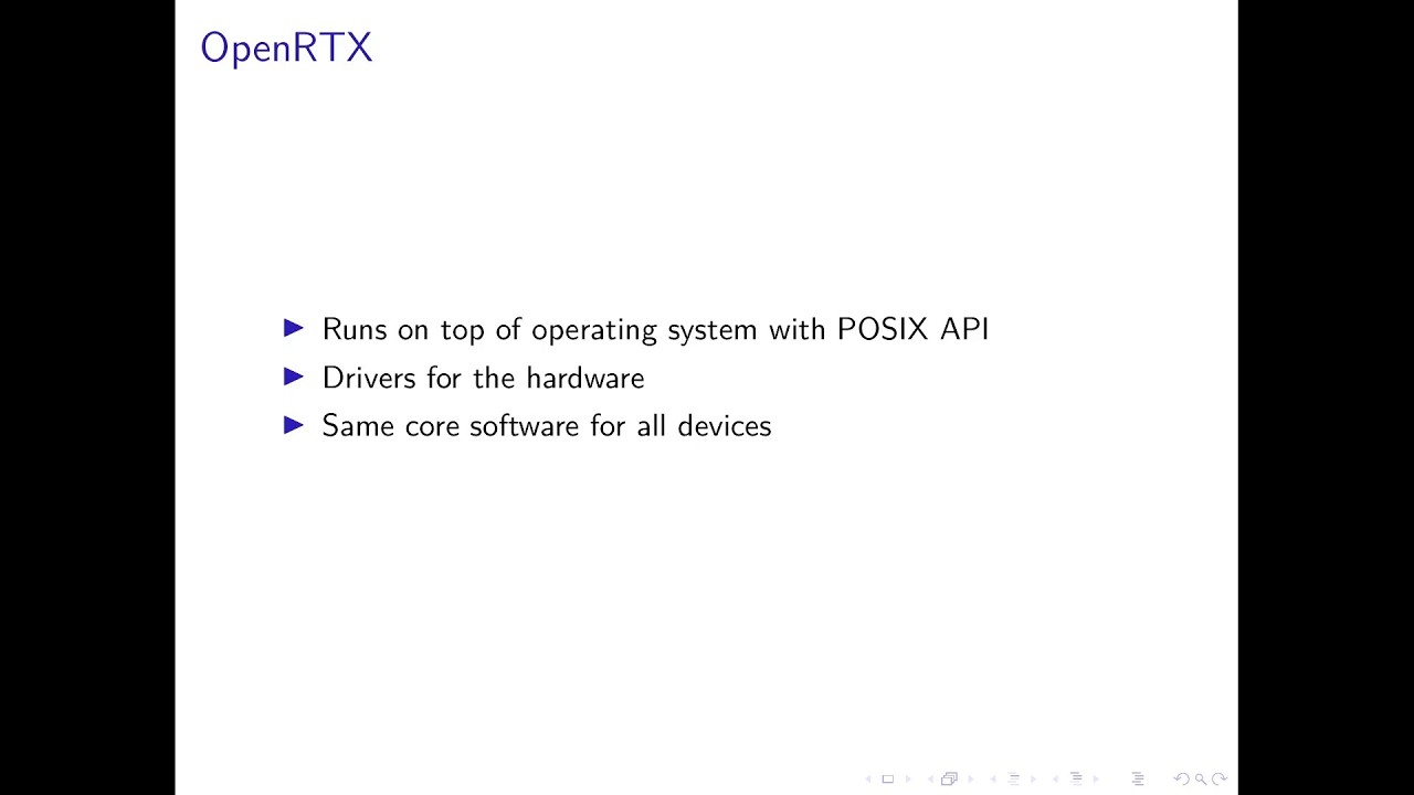
The video introduces OpenRTX, an open-source firmware project designed specifically for amateur radio operators to run custom software on commercial radios. Unlike traditional commercial devices where the operator is restricted to pre-loaded functionality and a limited user interface, this initiative leverages the fact that in amateur radio, the license belongs to the person rather than the device. This distinction allows enthusiasts to build their own hardware or, more commonly now, install custom software onto existing equipment. The project addresses the limitations of commercial radios, which often lack the flexibility and intuitive interfaces required for experimental use, by providing a portable firmware solution that runs on top of an operating system exposing standard APIs. This architecture separates device-specific drivers from the core logic and user interface, making it easier to adapt the software across various hardware platforms.
To demonstrate the process, the presenter focuses on the Ratel RT4D, a budget-friendly DMR radio priced around forty euros that supports both analog FM and digital voice modes. The journey to customizing this device involves careful disassembly and documentation of its internal components, revealing an ARM-based microcontroller, a specific DMR chip, and a common FM transceiver used in other popular radios like the Quanhang UK5. A significant part of the reverse engineering process involved understanding the proprietary flashing mechanism, which was achieved by analyzing the vendor's update tool, recording the communication over the UART bus, and even decompiling the bootloader. Fortunately, the vendor provided a schematic, which simplified the hardware analysis, allowing the presenter to identify calibration data storage in SPI flash and address issues like missing resistors for USB charging.
Once the hardware was understood and the flashing process mastered, the presenter wrote custom drivers to bring the device to life, starting with a simple LED blink test. This led to implementing drivers for the display, keyboard, and backlight, as well as creating a backup system to recover critical calibration data if accidentally erased. The ultimate goal is to integrate audio and radio drivers to create a unified experience where software can manage both transmission paths without conflict. By doing so, the radio gains a modern, intuitive user interface suitable for amateur use, supports new digital modes like M17 and APRS packet reporting, and even offers accessibility features such as voice prompts for visually impaired operators. The presentation concludes by highlighting future possibilities with more powerful devices and the potential to bring this open-source ecosystem to other commercial radios that are currently locked down by manufacturers.
Read the full video transcript
Okay.
Hi. Today I'm going to present to you
Open RTX and how to run custom firmware
on commercial radios.
So first I will start with a few
questions for you. The first one is for
everyone who also was in the last talk
who here already knows something what
image radio is.
Okay. So mostly everyone. So I can keep
it a bit shorter for the information
about it. Then who here in this room is
actually a licensed [snorts] amateur
radio operator?
Only one. But that's fine. You don't
need to know much about amateur radio to
understand this talk.
Then who in here has already fleshed
custom firmware onto any device?
So everyone that's good. We need to run
more of uh of our own software on
devices. Um and who in here has already
written or customized some firmware?
Okay, only one. But that's why you're
here and learn something about writing
custom firmware for devices.
So first I will give a quick overview of
the relevant topics of amateur radio. So
in amateur radio the operator is
licensed and not the device. And amateur
radio allows us to experiment with uh
radios and with that we get the rights
to build our own hardware. But with
modern devices we can also just build
our own software and put that on already
existing devices and as we are licensed
we can then use the devices with our own
software.
Uh there are multiple commercial radios
available. There are some of the bigger
manufacturers which produce specifically
devices for image radio. They are
normally relatively nice to use and
cater to imager.
But then there are also radios for
commercial use. They have often
overlapping frequencies with the
frequencies we are allowed to you use in
amateur radio and that allows us to also
use this devices but as they are more
catered to commercial operators their
functionality and user experience is not
uh that it doesn't cater to the image
radio operator because normally as in
commercial radios you get a radio you
get told you can press the button wait a
few seconds and then talk to someone but
we do more with our radios
And the user experience and UI is
normally then also not that great for
us.
Then there is Open RTX. Open RTX is an
open- source firmware for radios. It's
made from and for M radio operators.
It allows us to extend the capabilities
that the radios have by writing our
software and extending it and adjusting
it to what we want. And open RTX is
easily portable to other devices because
it runs on top of an operating system
that exposes the posing API. So we have
uh drivers for the hardware that are
mostly device specific and then the rest
like the UI and the uh the logic on how
to interface with things is handled in
the firmware. That's the same for all
the devices.
Uh now we get to one specific device. I
at some point found out about the Ratel
RT4D. It's this device I have here. It's
a DMR radio. DMR is a digital voice
mode. And it was on sale for €40. And I
was intrigued because €40 for a radio
that can do digital is quite cheap. What
is in it? I wanted to know more. It's
what I found already online is it's for
144 and 430 MHz. So we can use it for
image radio. It does FM. So uh normal
analog voice and it does DMR which is
digital voice but there was not much
more information available at the time
when I looked online. Normally for
devices that have a radio in them you
can go to the FCC website and get some
more insight about the device like
internal pictures of the PCB. So you can
already see what uh components there are
in the radio but there was no such
information available or the vendor has
uh put it under NDA so you can't get it
directly from the FCC and they have to
keep it hidden from the normal user.
So once I got the device the first thing
you do is you turn it on check that it
works and then you take it apart. That's
what you do when you want to run your
own uh code on it. And when you take it
apart, you then document what's in the
device and what you can find there. So
on the front there is not too much
interesting. We can see the display, but
there is no information about what model
of display that is. So we have to find
out about it in another way. And there
is a um an FM receiver there for
commercial radio. So your normal radio
that you can also receive in the car,
the device can also receive.
But then we get to the backside. There
are some more interesting chips here. So
I've marked five of them for now because
this those are the most interesting for
us. We have an ARMbased AT32
microcontroller in there that runs the
firmware. So it's already with ARM quite
common. So writing our own software
doesn't need any special compiler or
anything because you can just use an ARM
GCC compiler to write that. There are
other microcontrollers where you then
need to get a special compiler from the
vendor of the microcontroller and that's
harder to work with.
Then there is a second chip that's as
far as I understood so far does DMR and
it's also an AR microcontroller. When
you go to the vendor website of the
radio, you will find an updator for it
and then there is just a 2 megabyte blob
of firmware for it. So there is quite a
bit of power in there.
It also has an SPI flash for data like
the uh calibration data for the radio.
So to get the frequency right and to get
the power output right, there is
calibration data in there because every
radio is a bit different and even though
they have the same chip, you need to
calibrate them.
And then the actual radio chip is a
Beacon BK4819
FM transceiver. If you have heard
anything about radios in the last few
years, there is the Quanhang UK5. It has
the exact same uh transceiver. So, it's
quite common for now in multiple radios.
[snorts] Then there's also USB charging
IC, but sadly the manufacturers forgot
about adding two resistors to it. So,
you can only charge it with dump
chargers.
[snorts]
So for collecting information about the
device, first is I want to know how to
update the firmware. For that we have
multiple ways to go about. We can first
just record the flashing process either
with an oscilloscope or on the laptop
itself with something like S trace to
see what's going on on the UAT bus
because it uses UAT for its updates.
The second thing we can do is actually
reverse engineer the flashing software
that's running on the PC and see what it
does and how it communicates with the
radio. Or once we have actually access
to the radio and get the bootloader, we
can try and decompile the bootloader and
see what it actually expects from us and
what it wants to receive.
Uh then the next thing we need to get
stuff running is we need to know more
about the hardware. So for that yeah we
can check the FCC website but that was
already not that useful with this device
and we can open the device and uh
document what IC's there are and how
they are connected. And the third thing
we could do with the hardware
information, we can just go to the
vendor and ask them, can we have a
schematic for the device?
And then once we know the components
inside, we can check their data sheets
and see uh what they expect as a
communication and what bits and bites
you need to send it to get it working.
Or we can here also probe the device and
see what the microcontroller so far does
and how it communicates with the chips.
>> [sighs and gasps]
>> And we can also try and reverse engineer
the firmware to see what is implemented
in the firmware and how the firmware
communicates with the chips. Uh
luckily this vendor was quite nice. I
asked them for the schematic and I got a
complete schematic of the device. This
is just one page where you can get all
the components and the pin out of it. Uh
sadly they had some PDF which is just
one page with every page on this one
page. So it's not too nice to view in a
PDF viewer but it's great to have a
schematic because it saves a lot of work
and you don't need to do everything by
hand.
So now that we have information
available we can get our code to run.
For that I took a look at the flashing
tool. Luckily also this is a net
application so it's easy to reverse
engineer. you just throw it into some uh
tool. There is I think it's called
Avalonia Spy that just then shows you
more or less the source code of the
application.
Uh we can also then record the flashing
process because how they implemented in
software was quite convoluted and not
too easy to understand.
And with recording it, you can see at
first it connects to the device. It
tells it I want to do an update and then
it erases the flash with a command. And
once the flash is erased, it will just
send the firmware block by block over
and that's basically it.
Uh in the flashing tool, there's also
the original firmware in it because they
will send out a new flashing tool with
every update and the firmware is
actually in a string in the binary as an
Intel hex file that they then convert to
a binary in the code [laughter]
because why not?
>> [snorts]
>> So with knowledge about how the flashing
process works, I could then write a
flashing software so that I can flash
the device on any uh PC because the
original net application was also just
for Windows. Luckily, it just uses the
UAT port. So running it in W does also
work and I could debug it from that
side. But now we can flash the radio
from any operating system.
So now that I know how to flash the
device, I need to find out more about
the microcontroller and the uh the
address of the of the application. So I
need to know where to link it to so that
once the application starts up and uh it
will jump to the address of the
of our main function, it will be an
absolute jump. So it needs to know at
which absolute address the binary in the
end will be on the device. And there are
also luckily as it was in the Intel hex
format it has at the beginning a small
information about where the binary is
actually linked to. So we can just take
that address and put it in our own
linker script. So it will just then
work.
So the first uh firmware like like
everyone does when you get an Arduino or
something is you just let an LED blink.
For that we need to write some GPO
drivers to actually toggle the uh LED
and we also need to write some uh delay
drivers to get delays to have a
knowledge about time and when to turn it
on and off. This doesn't need to yet be
calibrated because we don't care if the
LED is 1 second on 1 second off and if
it's actually 2 seconds. It just needs
to blink in some way to see our firmware
is running.
We have a blinking LED. We can then
continue and implement a UI driver and
with a UI driver we actually have
birectional communication with the
device and with it we could now dump the
original bootloader.
Sadly there is also not much more
interesting stuff in the bootloader just
boots up erases the flash and then you
can flash something. There were some
other codes in the flesher but they are
not used by the bootloader. Oh.
Uh, now that we have something that runs
on there, we can write more device
drivers like the display driver and once
the display driver is working, we also
already got some output from the
display. So, we saw the pixels are
already there. There I was also lucky
because the used display that they had
in the device is a one we already had a
driver for. So, I can just take that
driver, adjust the initialization
sequence, and it just runs. That saved a
bit of work. Then to add a keyboard
driver, the keyboard is also like normal
keyboard more or less matrix and you
just do matrix scanning on the according
GPIOs.
The next thing I did was implement a
flash driver to actually get the
calibration data of the flash because if
by accident I would erase the flash,
getting uh the calibration data back
would mean I had to manually calibrate
the device and as there is no process
for that. It's more or less data that's
specific to the device. I could flash
something from another device but uh
then uh it might not be a good
calibration.
And the last thing I did was to get the
uh backlight driver because it's a mono
LCD screen and without backlight it's
quite dim. What's still in the to-do
list is getting the actual audio and
radio driver to work. That's intertwined
because the radio chip also has access
to the audio. So I need to make sure
that when I want to play audio, the
radio isn't playing audio.
And as we already have uh drivers for
this chip implemented but for different
devices and everyone is specific. I want
to have one generic implementation that
I can then just tell do this and every
device can use this but that's still
ongoing.
So what new features then do we actually
get when we have our own firmware on the
device? We get a UI that's actually made
for image ready use. So, it's rather
intuitive to use instead of the
convoluted um menu structure they had
before where it's multiple menus deep
and quite confusing to use. And if we
get actually access to the radio receive
and transmit path and also the audio
receive and transmit path, we can do
custom modes in software basically on
the microcontroller. So with that we
already have an implementation for APRS
which is automatic packet reporting
system that's more or less uh you can
send packets from the radio and receive
packets but that tells you this is my
location or this is the weather. So
that's quite an old protocol but the
devices couldn't do it before. Something
that we also have implemented is M17.
M17 is an open-source digital voice mode
and at the moment open RTX is the only
implementation that actually runs on a
radio that can do M17 and in the future
there can also be other modes. If
someone wants to try and play with radio
they can just implement something in
open RTX and then use it on the devices
and what we also get is accessibility
because now we can actually do voice
prompts. So vision impaired or blind
operators can also use the devices.
And one big feature, you can put your
tickets for events and uh tickets for
your merch on the radio and collect your
merch with it.
So in the future there are some other
interesting devices. I got an any tone.
That's quite interesting because for
some reason they put half a GB of flash
in there to just use and also have quite
a powerful microcontroller. It's also
ARM. So I'm interested what we can do
with that device also because having a
lot of power means we can implement
quite some interesting modes of it.
And there is also some other operator I
think from Austria. He has one radio
from a big commercial vendor and we
should also be able to run our software
on that which is not quite that common
because the big vendors normally protect
their devices so that you cannot easily
put your own firmware on it.
Okay, so here's then some links for the
Open RTX projects and thank you for
listening. If you have any questions
feel free to ask. No.
>> Do we have any questions?
It doesn't look like that we have any
questions then. Thank you for your
attention.
[applause]