Video summary
ContainmentFOAM is a collaborative OpenFOAM-based tool developed since 2015 by researchers, PhD students, and industry partners specifically to address nuclear safety applications within complex containment structures. Rather than functioning as a standalone system code, it serves as an advanced add-on for OpenFOAM v9 with plans for future integration into version 11, designed to simulate severe accident scenarios using the "defense-in-depth" concept where the containment acts as the final barrier against fission product release. The primary objective of this framework is to overcome limitations found in standard system codes that rely on simplified one- or two-dimensional approximations by integrating comprehensive multi-physics models into complex three-dimensional geometries, thereby enabling detailed analysis of combustion events involving hydrogen and carbon monoxide, shock waves, dynamic pressure effects, and condensation processes.
To manage the immense computational demands inherent in such high-fidelity simulations, ContainmentFOAM employs a strategic multi-scale approach that balances accuracy with efficiency through specific modeling techniques for geometry, numerical stability, and physics implementation. The tool utilizes porous media approximations to treat smaller structures while refining meshes only around critical features like doors or burst disks, and it implements "a posteriori" time-step management triggered by system events such as the opening of a safety valve to prevent crashes during rapid transients. Furthermore, advanced physical phenomena are handled through wall functions for condensation in non-condensable gas environments, treating fog and aerosols as passive scalars with drift velocities, while radiation heat transfer is efficiently calculated using a Monte Carlo solver that tracks photons across complex geometries rather than solving equations per energy band to handle spectral properties.
The framework supports the integration of various technical systems, including burst disks, passive autocatalytic recombiners, and pressure suppression systems like those in the IRIS concept, often by coupling them with standalone codes via Functional Mock-up Units for system-level interactions. To ensure consistent case setups and prevent errors during the complex process of mesh mapping between fluid flow and radiation domains, a guided Java-based workflow is provided alongside repository resources such as documentation, test cases like ISP47, helper tools including CFMeshPlus, and solution monitors for log visualization. These standardized workflows also facilitate community contributions and bug reporting, ensuring that the tool remains robust and adaptable for collaborative development while providing essential features for initialization via TopoSet and uncertainty quantification to standardize analysis procedures across different teams.
The practical capabilities of ContainmentFOAM are demonstrated through a successful 20,000-second transient simulation of the PATENT model containment in Frankfurt, which showed reasonable agreement with experimental data despite uncertainties related to stagnation zones. This comprehensive approach allows engineers to screen severe accident sequences quickly using fast tools before identifying high-risk compartments for detailed computational fluid dynamics evaluation within ContainmentFOAM, ultimately feeding results into combustion solvers or system codes for a complete safety assessment. By combining these advanced modeling strategies with robust workflow management and extensive documentation resources, the tool provides a powerful platform for analyzing flammable regimes and dynamic pressure effects that were previously difficult to capture accurately in nuclear containment studies.
Read the full video transcript
please thank you very much Vladimir good
morning everyone
welcome to this uh I would say practical
introduction to containment form so I do
not want to go into all the theoretical
details that we have but I just would
like to give you a flavor on what
containment form actually is and what
one could do with it and I leave the
details for your
own studying and of course questions in
the coffee breaks or whatever
so you will see my name written here but
of course our containment form has not
been developed by Me Alone
um I have a list of people we work
together since 2015 primarily on
containment form
PhD students Master students interns we
had the trainees for software developing
all of them we came together
contributing the one or the other part
on containment form and
this being said in case you're
interested to contribute of course
you're very welcome just to get in touch
and propose the one or the other detail
Anya
okay
can hardly do anything about it
okay I can try to speak louder maybe
that's it there are also a number of
projects sponsoring the one or the other
activity I don't want to go in in all
these details but just again to
highlight that activities like Encore
really helped to um to drive such a
project forward by
say enabling exchange among peers that
are in the same situation we develop
best practices and so on
and last but not least there are also a
number of personal collaborations helped
us a lot to to drive this thing forward
so if you want to get it um there's a
very easy way we put it into a short
link
go.sha.e containment form and be aware
these last four letters are capital
um or you can take this QR code and you
will end up in the repository and it
will follow the same way like you are
used from yesterday you will find the
all W make script you just run it and it
will install a containment form as an
add-on to your open form version and
this time it's not ESI but the
foundation Version 9 that we use as a
basis so unfortunately you have to to
install a second one on first
okay so for today
um for the next I would say one hour one
hour 15 I would like to give you
um
any overview on containment form uh
being an example on how to tailor open
foam for a nuclear safety application
so we will discuss a bit on what
containment form actually is what we
develop it for
um and on this basis we can also then
see which kind of functionality open
form gives us which kind of
functionality we need to tailor for our
purposes and how actually we did it
so with this of course we have to
discuss a bit about the background I
assume you're not that much familiar
with CV accidents and containment
analysis so I will dive a bit into this
and I will also here and there have a
quick look on the model the equations
how we put this into the code and how it
actually looks like from a user's
perspective
and finally also I will highlight a bit
where the journey with containment form
will go to
so be aware this is just the tip of the
iceberg within 60 or to 90 minutes not
much is possible but there's much more
hidden and of course this is to be
discussed
so the outline will be uh first will be
the Practical introduction on the the
background the applications we aim at
then briefly on the strategy we're
following for developing containment
form and the
particularities I will briefly touch the
theoretical background I have a lot of
slides here but I don't want to go each
of them explain deeply the physics but I
would just tell you that these are
special models we have here for good
reasons and um
how actually we did it so kind of
example
on the process
I will then at the end give you some
insights in let's say the framework we
built around containment form so it's
not just a code it's for us it's also a
collection of best practices on how to
use the code how to do these
developments together
and how to work with the code on
practical applications so we have a kind
of guided workflow tool that we've
developed we have a solution monitor
that helps us to analyze the the
solution on runtime I would like to show
this to you before I conclude my talk on
our work
okay so what's a severe accident what's
the target application are there many
ways to explain it I I would like to do
it by the way of the defense in-depth
concept which is probably well familiar
to all of you
actually
um a concept of staggered barriers that
should prevent the release of fission
products to the environment these are
the fuel metrics the fuel claddings the
reactor cooling system and finally the
containment
so we have again also um a set of
staggered barriers on an organizational
and Technical level that will prevent
that those barriers will fail and we've
seen these different levels you see here
um the first three levels they are what
we call in the design basis so a lot of
engineered safety features that will
simply prevent
that the accident is um progressing And
the tried to stabilize the plant while
when we are approaching or we are
crossing this line we are going into the
level four it's assumed that the
engineered safety features also failed
and the plant is going into severe State
meaning that the the fuel is being
damaged
and in this um what we will easily see
is that the containment becomes the last
barrier against the release of fission
products and of course it is of utmost
importance to make sure that it will
stay intact and there's no no release so
in order to do that we need to
understand all the processes that happen
in the containment and that May
challenge in its integrity
and one thing that's really
um a big threat to the containment is a
combustion event
something like what happened in
Fukushima here it happened not within
the containment it happened in the
building around but at least it drove
our attention to uh that that kind of
risk again
so you know whenever there's uh steam
getting in contact with a hot metallic
surface it can corrode this or oxidize
this surface and produce a lot of steam
hydrogen which is released to the
containment
and also in the later phase of an
accident when the modern corium is
getting in contact with concrete it will
decompose the concrete and produce a lot
of hydrogen carbon monoxide which are
combustible gases
so if you look at this um from the
perspective of a ternary diagram so you
see here on the lower axis the fuel on
the left on the right Axis the inward
gases on the left axis deoxidizer we can
characterize a kind of regime where
um the gas mixture itself is flammable
and there's even a smaller regime where
the gas mixture can undergo a detonation
um then we can put our accident sequence
in this uh this plot and you see
actually we will start here somewhere
with a with a dry atmosphere in the top
we will release a lot of steam for
example in the loss of coolant
will at some point start producing and
releasing hydrogen so we are going a bit
more away from the axis
up to a point where the release of steam
and the condensation of steam and the
containment is balanced and then the
atmosphere is drying out again
and we will run into this uh potentially
flammable regime
this is actually not a big problem as
long as the combustion process that is
resulting or can result is a slow
process that means the energy is more or
less transferred into heat but when it
accelerates and becomes a fast
combustion we can have Dynamic effects
shock waves and at this point let's say
the pressure may be higher than the
paicc the adiopathic as a caloric
complete combustion pressure that we use
to to design the containment
so these things they heavily depend on
the geometry on the turbulence of the
floor and of course need some
three-dimensional understanding
there can be other effects like standing
Flames which result from let's say
continuous release is a local phenomena
also again benefit from a
three-dimensional representation
when we do cfd in such an environment of
course it's not the Standalone tool so
it just embeds into an analysis chain
starting from a very um let's say quick
running tools that help us to to screen
out the most penalizing sequences
um to select those which are let's say
of high interest for our analysis to
prepare Source terms that we can use in
the more detailed codes
and then once those um those scenarios
are found there will be also again a
let's say a set of analyzes with
increasing detail to to understand where
potential risk can be and how safety
measures Safety Systems can be can be
implemented
this step we can go and run cfd to study
the three-dimensional evaluation of the
flammable cloud and of course we can
give this information
to um combustion solvers which are also
for example made on basis of open form
but you can also simply use Imperial
criteria to say acceptable
non-acceptable and iterate the process
of improving the the safety concept
and finally also this
let's say three-dimensional combustion
loads can be given to the fluid
structure interaction for very refined
assessment
so in this context cfds um I would say
somewhere in between an experiment and a
system called analysis so it will
um not replace the system codes for sure
but it will help us to to gain more
understanding
um for example when when we use
experiments to validate system codes so
we can get insights where we don't have
measurements we can have to design
experiments we can help to design the
nodalization scheme of of system codes
can have to um
let's say get the best out of the
experiments by doing some preliminary
design studies we can help upscaling
experiments I mean you know cfd doesn't
have any length scales in the equation
so it's easier to scale up than the
system codes
and also it can help us to understand 3D
effects which are simply ignored in the
simple 1D or 2D approximations
the challenge here is of course that we
have to isolate our problem and get the
proper initial and Boundary condition
and these of course with a much higher
level of detail than it would be needed
for a system code
often what we do here is apply cfd to
something that's a bit off standard so
it's not easy to use models that come
from let's say IC engines or from
aerodynamics
um
turbo machinery and apply them to
containment analysis without questioning
their validation basis
and also getting a hand on the feedback
of the system so this is for me
everything that's coming from the the
containment as its own from The
Operators from the safety systems that
are installed this is something which is
typically not a standard piece in a cfd
simulation
so I would like to show you a few
examples we did starting with an
international standard problem that was
run in a would say quite application
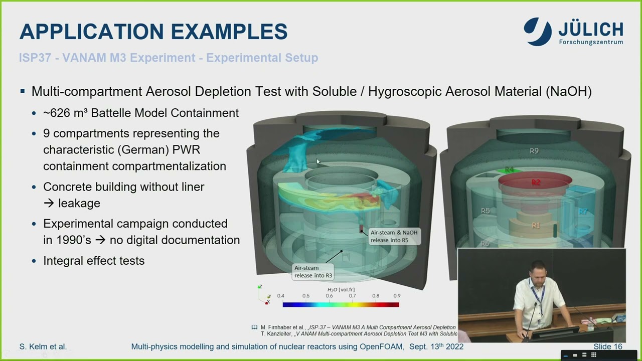
oriented setting so this is the Patel
model containment
a former test facility in Frankfurt in
Germany
which had a volume of roughly 650 meter
cube and it was compartmentalized in a
way to mimic the rooms in a German pwr
containment
the concrete building so there were some
leakages which were not not really
Quantified this was not easy to to
account for in the simulation and left
some questions but at the end it was a
nice setting for us to to test the model
on some realistic application and at
least with some experimental references
um it was a complex transient you see
here for roughly 100 and something
thousand seconds and what we did
actually was we were just studying uh a
quick injection of steam and aerosols
microscopic aerosol material and then a
depletion phase where the system is
coming to rest steam is condensing and
the aerosols are settling and afterwards
there are some other injection phases
with different modes which we which we
did not consider so far
see a cfd typical mesh so we have some
refinements where we assume gradients
like the jet flow here or the boundary
layers close to the walls and a typical
mesh size of roughly two and a half
million cells in the fluid
which I would say is some
close to a standard cfd application in
this case
open form gives us a nice tool to
initialize such a case so you can
imagine we did not want to run 17 hours
preconditioning of the facility just to
come up with a good initial condition
for doing this work so there's a tool
that that Carlo already mentioned that
we used in the in the very first
tutorial which is called Topo set this
allows us simply to pick pick up a set
of cells and then do something to the
cells so what we did here we we selected
all those rooms the compartments we took
a representative measurement of
temperature
concentration and so on
and we applied this filter to select all
the cells that are either in the volume
or let's say within a certain thickness
around the volume so we could give an
initial field to the structures and the
fluid then we let this diffuse to get
some initialization for the solid
structure temperatures we run a short
transient to get an initialization of
the three-dimensional flow field
and with this we could jump directly
into the interesting piece of the
transient so this is a way we also think
of using it later within our application
to containment get some initialization
from the system site put it into
containment form and then run a certain
time frame of the transit
looking at the experimental data I would
say the results are okay still
improvable but given the uncertainties
we have I was pretty satisfied doing
this so we were able to get a I would
say reasonable agreement of the
temperature field above the injection
and below it was a bit difficult here we
have a lot of stagnating flows and weak
flows so it was giving us a higher
differences all in all I was pretty
satisfied
looking at the distribution of aerosol
material I would say
um we captured the initial Peak
during the injection phase but the
depletion rates were somewhat looking
different
but um yeah this
just made based on three samples that we
have during that time so there's a huge
uncertainty here but still I would say
the tool was generally able of capturing
the phenomenology with the one or the
other let's say overestimated or
underestimated tendency
what I would conclude is that this kind
of first of its kind application of
containment form with a lot of different
physics inside was really challenging
but it was possible and doable and
overall the results were um plausible
and we could showcase that running such
a transient of 20 000 seconds
it's absolutely possible within a
reasonable time and reasonable time here
would mean 128 course and something like
a 20 days run time for this 20 000
seconds
so here we achieved something like 400
to 700 seconds per day depending on the
face so you can imagine if you have a
fast injection time steps are small it's
rather slow and in the stagnating phase
you can easily ramp up with the time
steps
so um I would say the method itself it's
application ready but it's something
that's still expensive for long
transient and we we need to find good
approximations for modeling the the
injection even or in particular when
they are for high momentum
we are currently putting this into
um let's say a full-scale containment
analysis within the heiko project the
European project
which aims at analyzing the combustion
risk
in let's say the the Western types of
containments in Europe
and um
we want to do this with particular focus
on the late phase so where we have
hydrogen and Co and the idea is here to
again screen two different scenarios
using Lumpur meter codes having a fast
analysis of them in 3D called Gothic to
identify those
um let's say compartments and the time
sequence which are for interest and then
go into detailed assessment with cfd not
to compute our combustion process at the
end but to give some idea on how
effective different mitigative
strategies are and um
also to to see uh let's say if the
instrumentation that the operators have
will allow them to um to really
understand the situation in the
containment and and take the right
decisions
in a similar fashion we went together
with colleagues from Munich um to
analyze the combustion process so they
develop a solver which is called
explosion Dynamics form it's a
compressible solver which allows to to
Really solve for this shock waves
and the the way
um the initial step was similar to what
I presented before running the system
called mapping the information on a 3D
mesh and then simply igniting it to
assess the combustion loads but here we
miss an important factor and this is the
turbulent of the floor
um shortly before the the combustion so
turbulence leads to a wrinkling of the
flame surface and this will then speed
up the reaction rates and lead to
acceleration of the flame
so the idea we had here was simply to
add another intermediate step after
mapping the data running containment
form for a few minutes just to develop a
certain flow field develop um
an initial turbulence level to then give
to the combustion code and assess the
decombustion
similar things in the non-nuclear field
so um this is a technology demonstrator
plant that we build in our campus um
it's a very prototyping in many senses
and of course it combines a lot of
hydrogen Technologies and again here
it's uh very important to make sure that
no combustible mixtures can occur
so we put this into containment form run
different accident scenarios to see how
the mitigation strategy is in place
something like active venting
safety shot shut off valves and so on
they will prevent formation of flammable
mixtures so um
I will not detail this but at the end
cfd in such an application is really the
tool to go since this is completely new
future will go a bit more into direction
of smaller modular reactor Concepts
again more on the focus of light water
reactors since this is what we developed
most of the models in containment form
four and we picked out representative
types of those reactors
um which have on the one-sided dry
containment with a lot of passive safety
features like you see here the iris
concept this is a small containment
um which can go up to higher pressure
than a classical one
and actually what happens if there's a
loss of coolant here is that um
the driver will be pressurized the gas
it's a non-condensable plus d will be
perched into this pressure suppression
pool the steam will be condensed the
non-condensables accumulate in this gas
space here will be brushed partly into
the liquid gravity makeup system and by
this let's say the the pressure in the
driver will be a function of let's say
in balance with the pressure in these
two gas spaces here
so you can imagine you will never be
able to predict this if you are not able
to predict the pressure in those gas
spaces here as well
it becomes a bit more complex in the
later phase of this accident when
there's a pressure equilibrium in the
driver and these gas spaces and the
steam production rate the Decay heat of
the fishing products will go down that
means we will have a reversal of the
flow so now um water will be perched
over from the pressure suppression
into the driver and accumulate here in
the cavity so this will enable some
cooling external cooling of the reactor
pressure vessel
and also lead then to the fact that the
part of the driver is filled up with
water so it will affect the free volume
that we have
sold in all this poses quite some
challenges on the model so we have to
somewhat consider this system feedback
we have to go probably for a more
complex way of modeling condensation
and also we have to to consider that
there are no non-condensable gases they
are simply perched over into this um
this volumes here
another concept is um these submerged
containments like we have it for New
World or new scale which rely on in the
late phase of the accident on an
external cooling of the containment
removal of the decayed into the
surrounding pool as an ultimate heatsink
and here we have a natural circulation
on the outer side this is a very tall
containment something like 25 meters
tall
at a very high rally number and again
this is something which is completely
out of the the validation range of the
empirical correlations um that we that
we use today
so here cfd can help to um to study this
also in link with the processes on the
inner side of the containment
can help to study the effect of let's
say a non-planar surface as you see here
in the in the cut drawing
and it will also help us to understand
how to to fit this information then into
system codes for more
comprehensive analysis
so you see there are a lot of challenges
to solve when we wanted to address some
problem like this with cfd and I briefly
want to highlight how we approach this
service this containment form
just to say it's um it's a coordinated r
d effort so we try to develop all the
things having the big picture in mind
it's not like individual pieces here and
there that we can plug and play but you
will see later we will really have to
interact with the different models that
we are doing
it's a multi-scale application and to
some extent it's also multi-physics
application as you will see later and
it's very important I will stress that a
couple of times is that if you do such
an analysis there's no way of
simplifying the problem isolating a
single piece of physics but you really
have to do all of these things to be
representative
so in this way let's say the whole or
the the system model itself it is as
strong as the weakest element and um
that means let's say the slowest model
determines the time we're running and
the courses model of course will
determine the accuracy of the whole
result so this is something to be
addressed in the model set
came up with a baseline set of models so
you will see containment form as not too
many models at all but all the things we
have um they are there for a good reason
and we're trying to understand
limitations of those models rather than
optimizing them for a very specific
purpose
having this limited set we can give a
better guidance we can limit our
maintenance efforts so again we will not
put everything that's available into the
code but we will stick to something
that's
to our opinion the most useful model set
and also we came across the point that
there are many things which are done by
everyone it's repetitive
um something like case setup monitoring
and evaluating a solution so we've
provided some tools or we are developing
within containment from some tools to um
to ease this process and Implement a
certain set of standards so there are
common post-processing functions for the
basic things like heat and mass balance
there are recommendations for data
handling minimizing IO
and also we are working on on a
framework to quantify uncertainties
within the validation runs so that these
sort of things they are standardized and
repeated
if you look at the phenomenology we
discussed the one or the other thing
here is what you see clearly if you look
at the containment it's uh it's a very
complex three-dimensional geometry a
multi-compartmented some of the
compartments they are separated by doors
and burst disks so these sort of things
can open during a transient and form new
flow paths and also we have a wide range
of lengths and time scales coming from
the system as it all down to the physics
that we are solving
similarly on the phenomenological side
there are many things to consider
um we are going through a broad range of
flow regimes if we really start with the
blowdown
um
you can end up at very slow flows which
are primarily driven by local
differences in density and then they can
be even stagnant zones in in the
containment
so there are a lot of physical phenomena
interacting
um with themselves but also with the
system feedback so the effectiveness of
passive safety features for example
again to be loud here if we want to
discuss all these things there's no way
of
simplifying the problem too strongly we
really have to consider all of these
things in the model
so I I wanted to brainstorm a bit but I
will be fast on this to save some time
there are a lot of things that will
affect the containment atmosphere flows
and mixing the let's say um
change of temperature composition which
it uses buoyancy and also the the
pressure heat and mass balance and just
to give a few things I had in mind of
course this is heat transfer heat
exchange with all the structures in the
containment this is heat transfer within
the atmosphere primarily thermal
radiation these are safety features like
passive autocadilly degree combiners
containment coolers which are in many
things they can be sprinklers
uh we have this um
doors and burst discs which will heavily
affect the flow pattern when they open
we have operator actions some Logics
something like if you reach that certain
pressure activate the venting system
that needs to be um considered and we
have a lot of input from the primary
system which is not part of containment
form it's simply as an input from from a
system called something like the the
steam release rates
um
evaporation from sums so you will see
containment form is a single phase so we
are not not modeling accumulation of
water we just take it from the system
side
it losses from the erector cooling
system components heat and mass release
from molten chorium concrete interaction
these are things we we cannot do we just
rely on on external input
of course all this is linked with the
atmospheric mixing processes but also
there are some interdependencies of the
models so simply to say
um bulk condensation fogging and aerosol
transport are very very tightly linked
um and at the end this will also drive
then the distribution of the Decay heat
the fission products in the containment
atmosphere which will induce buoyancy
locally Drive The Mixing processes but
there are other things like radiation
and fogging this will affect each other
the safety systems like Spa they could
evaporate the fork which is formed
somewhere so at the end there a lot of
dependencies between the models where
the models have to talk to each other
provide their output as an input to the
others
we put this together in a set of models
as you see here I won't go to all the
details but at the entry we defined a
baseline model for all these um
different phenomena the green check
marks are simply saying this is within
the release version we have for the
moment the yellow ones is something
that's still under work and will follow
soon
so to summarize containment form is a
package which contains some tailored
solvers for let's say fluid only and
conjugated transfer Solutions and also
we are now putting this um
face volume of fluid methods over here
we have a library of application
oriented models which are really
tailored for a specific let's say
thermal fluid Dynamic conditions and
applications
we have done quite some verification and
validation
unfortunately we cannot share the
validation cases since all the data is
somewhat proprietary but at least the
verification is part of the Repository
and we have set up a framework for
collaborative development
um for collaborative use of the code
that I will show at the end
when designing containment form we
designed it not to be Standalone part
it's um an add-on to open form version 9
at the moment it will be version 11
hopefully within half a year
um
and we did this in two ways the first
one was simply what Carlo mentioned
yesterday
identifying an interesting model in the
code cloning it and then changing it so
that we have a new version of it and the
other one was creating um separate base
classes that will provide us
functionality that was not there in open
form before something like multi-species
transport or condensation
and while we did this we were pretty
careful implementing a number of
plausibility checks so if you run it and
you will get a lot of errors and the
code doesn't want to start this is
simply because we did all these checks
to guide the user and prevent that
things are done which are inconsistent
with respect to the design of the models
so for example here you see that we we
check a combination of boundary
conditions just to make sure that
someone who wants to run condensation
does not forget to specify uh the right
boundary conditions for all of them
those um base classes they um
and also their derivatives they hold the
number of access functions which you can
simply call in the the equation stand
something like here for example we get
the diffusion coefficients from the
library we can get the condensation
rates from the the class and add this as
a new source term for example to to the
equation
okay with this I will quickly jump into
the theory and we can run to this pretty
faster I would say
um but before I come to the physics uh I
would have a very short excuse to the
geometric modeling of the containment
I mean a major feature driving the flow
is more or less the geometry of the
containment it's super complex and at
the end we need to consider this in the
geometric model but on the other hand
it's pretty clear the more details the
more features we involve in the geometry
the harder it will be to to run this and
the more expensive the computations will
be
so to give you some idea on how to
approach this um we take the geometry
here
we specify a kind of a maximum Edge
length this is a half a meter in this
case so the large cells you see here in
the bulk region
and then we we specify refinement levels
to resolve the uh the structures within
the containment so a refinement means we
are cutting a cubic cell into four
so you can imagine by refining the
rapidly increase the number of cells so
I would not go more than two refinement
levels that means my smallest Sellers
and Edge Links of 12.2 centimeters and
if I imagine I need at least two cells
to resolve a structure then this means
the the geometric feature links that I
can resolve is 25 centimeters so this is
pretty large actually for a cfd
simulation
if I do this feature resolving you see
it um here for example then that means
that I get a lot of small cells close to
the features and again when I then want
to extrude boundary layers to also
resolve the flow near the the walls
something like you see here I would just
extrude those small faces I have into
the bulk so this will multiply up again
the number of cells
so you can imagine that coming up with a
a usable mesh here is some
really a balanced between a lot of
different things to consider and in this
particular example here I came up with
something like six million cells for
um the fluid phase of the containment so
this is I would say pretty coarse
looking at the phenomenology but this is
already something that is challenging
for running transient analysis
so we need to find models that can
somehow handle on those kind of course
grids
so at the end we are trying to reduce
the number of equations to be solved we
are going for single phase we try to
neglect all those
um liquid parts we are using Iran's
equations not going for something fancy
like Les we use wall functions near the
walls to prevent the high boundary layer
resolution we try to add effects that we
cannot solve with the simple modeling
into the runs equations we have from
tracers like a fog or aerosols they are
simply passive scalars transported along
with the flow and wherever we have very
specific things like system models we we
try to use a course approach either
porous Media or some system coupling to
to represent all this
and you can imagine if you resolve the
containment with let's say a
characteristic length of 25 centimeters
you will lose a lot of structures
walking grids handrails all these things
pipings a lot of heat capacity that we
have that will condense Steam and
prevent
um pressurization so at this point all
these things have to be con considered
somehow in a porous media approach it's
no way of neglecting these things
it's so um
quickly go through the models um
we took a basic solver reacting forming
that was available with open form we
extended it by a multi-species treatment
so primarily adding molecular diffusion
here
doing so you you have to know that there
will be another term coming up in the
energy equation which accounts for the
the enthalpy which is diffused by the
diffusive mass flux here
and then we added some Source terms
which will um let's say be used to
integrate the one or the other model
um we set up a solver algorithm which is
close to um what what reacting form was
doing but at the end we we had also to
integrate all the models that we that we
will link and we do this in an implicit
manner so mostly the models are
integrated and updated within the the
people Loop
specific thing here when it comes to
multi-species flosses that actually the
density is in any equation and it will
change by nearly any equation so it will
change when we update continuity it will
change when we update our species
concentrations it will change when we
update the temperature field and it will
again change when we update the pressure
field
so we need to iterate around this a
couple of times meaning a piece of
approach is not possible we have to go
for pimple
um we Define the Baseline set of
numerical settings I will not go into
detail on this but if you look at our
test cases you will find that these FB
Solutions Fe schemes they are always
looking the same this is a kind of
consensus we had to make sure that
somehow these considerations are not
leading to some user effects in the
validation
we put in some nice feature for
um for system analyzes which I would
like to highlight here this is a kind of
extended time stepping management
so actually what open form does is
looking at the current number to reduce
or increase the time step and this is a
aposteroid treatment so it will simply
check what happened in the time step
before and adjust the the current um
current time stepping there's one issue
with it meaning a large time step does
not mean a fast simulation so
technically you can have a large time
step with many internal iterations or
you can go for a small time step with
less internal iterations and in some the
letter is faster
so what we added was checking the number
of pimple iterations the inner
iterations we need and by this also just
the time step
and again this is something that happens
a posteriority so whenever the
convergence was not good enough it will
reduce the time step but of course we
already did this convergence issues in
our city
our solution so the idea was to
um to have some kind of trigger where
our system models can tell the code
something will happen very soon reduce
your time step something like a burst
disk will open so this will rapidly
change the flow situation from a
stagnant or close to stagnant flow to
something that is very fast
so in this point we can change already
before this event happens the time step
to a small value and then come back
afterwards to this automatic treatment
and last but not least if you shoot a
simulation it's not usually it's not
fire and forget it's um
started you have to monitor it and of
course when it crashes this is a loss of
of computation time so here we added
another feature saying that if a Time
step is not converging
redo it with a smaller time step size so
this will help us to prevent any kind of
crashes that that may happen during
runtime
and we put in these controls into the
the controlled
they're Christian
nope
so we put in these some controls into
the control bit and tested it on a quite
typical transient I will come to this
later it's a pressurization transient
over 20 000 seconds we are running here
or again another International standard
problem and if we do this with all the
classical treatment and the improved one
what you actually will see is the the
classical treatment here in red it runs
partially on a larger time scale so you
see here the curve is straightly going
up
um but it often reaches the maximum
number of tolerable people iterations
well if we choose this uh new treatment
we will often have a smaller time step
like here and here but it will remain at
a low number of pimple iterations and at
the end we do more time step
Integrations but we reduce the runtime
simply because we are converging
um better than before
and this will
let's say to some savement of computing
time but also of course getting a more
accurate solution since we are not
exceeding our convergence limits here
I told you the case of the burst disks
so um we have the system events created
by the user or by the system models
themselves simply uh reducing the time
step keeping it on a low level and then
giving control back to the time step
management and again here we see that
this is very beneficial in such system
scale analysis
see on this simple example so when we
run here I'm pressurizing uh the first
chamber we can run on a pretty large
time step and then when the um the burst
disk fails the time step will be reduced
quickly if you do it by the current
number we can easily go up to current
number 400 500.
um and then we will have this fast flow
which is equilibrating pressure between
both arm volumes and you see here on on
this pressure plot if we do it with the
current number we accept this one time
step with a high numerical error we will
end up with a different pressure at the
end so this is an indicator for a
problem with the mass balance well if we
use the treatment here you will see that
actually we can much better capture the
reference results
however at a somewhat larger cost
so doing this is of course something one
has to adapt carefully but we will put
this or we have put this into our
solution monitor set so that the the
time stepping strategy can be can be
monitored and adapted according to the
Run
so we'll not talk too much about the
physics of modeling turbulence just tell
you um we're adding some Source terms
here into the equations you find it in
the source code in a very simple way
just adding this function which at the
end allows us to compute the source term
based on the model that we select in the
dictionaries either simple or
generalized gradient diffusion
hypothesis and then return this value
into the turbulence model so um not too
tough to um to add this
jump over this
um for condensing flows I said we did a
simplification which is reasonable for
large dry containments it's not so
reasonable for the small modular reactor
containment but what we assume here is
we have a lot of non-condensable gases
that will practically
um pause the the strongest transport
resistance of steam to the wall or to
the condensing interface
so here we can model condensation rates
simply as the diffusion process let's
say from the bulk to the interface
and the challenge here is um modeling
the turbulent diffusivity
this is done using the wall functions
um you will see everywhere in cfd people
using wall functions and this is very
um important for for that kind of
application since this will directly
affect the condensation rates that are
predicted
so the wall function does nothing else
than linking the value at the face our
saturation condition to the value at the
cell center and it is not doing this by
prescribing a value but prescribing a
flux
so in open form this is done by adopting
the um the turbulent diffusivity to
match these kind of analytical profiles
that are specified in in the wall
functions so we can get the turbulent
diffusivity from the wall function and
of course for condensing wall we don't
have to do this just for the species we
have to do it for temperature for
velocity for turbulence and so on so
there's a set of wall functions to be
applied along with the condensation
model in order to make this kind of
model work
um
another example um for open form for
let's say the ease of putting a model
into open form if you do it Implement
such a model in a in a commercial
software what you typically do is add a
source term to the governing equations
um that's straightforward but at the end
it does not really reflect the physics
so you can imagine if this is a large
cell things happening at the cell center
where you evaluate the source terms are
different and things on the face where
the flux originally is
so what we did in in containment form
was simply putting the flux on the wall
on the face this is nice because it
appears as a convective term in The
Matrix
awesome it's implicit treatment and we
simply model all the processes on the
boundary itself
so um
again to highlight these models they
they just work if you follow a very
specific way of specifying all related
boundaries for that patchware
condensation works
we validated it it was some giving us
good results and I just want to conclude
on this with an example of the isp47
again
um if you use wall functions and your
mesh is to cause your turbulent
diffusivities will be wrong or let's say
not correct enough and this may happen
if it's the course that you
underestimate or overestimate
condensation rates
here um in these phases where a high
condensation is occurring you may
overestimate the condensation rate
significantly
be aware of these arrows and try to
um to understand this by visualizing for
example the Y plus values
oh jump over to um fogging
so actually what we do is we take
another simple Model A thermal acrylic
equilibrium assumption we homogenize the
fork in a Cell we use it or we transport
it as a passive scalar and we use a very
simple model It's the Return to
saturation constant time scale model to
um
pick the condensation or evaporation
rates so we simply adopt our
concentrations to match the acceleration
state in each cell
so fog is then transported Again by a by
a means of a passive scalar it's the fog
volume fraction and we allow the fork to
drift relative to our mean flow to the
gas flow based on this drift velocity
term which is just resulting from the
fork from the forces like
track or on gravity
so
it's not tough to implement such a model
what we see at the end of the day
there's one parameter we have to give it
an input this is the diameter of the fog
droplets and it's very hard in a in a
let's say transient analysis to space
specify a constant diameter so um
what we went forward was to um to add a
simple population balance model
some piece of software available in open
form we just put it into our framework
to
to model also the growth and shrinkage
of these fog droplets so actually what
we do is we have the size distribution
of fog we
separate it into bins with a specific
representative volume and some interval
around it and then we have Source terms
that will account for the coalescence of
fork droplets so small droplets forming
a larger ones and also the change of the
um the bin due to evaporation
condensation
and we solve a number of these transport
equations then for each of those volume
intervals
so this is some
giving us a quite physical
representation it's slightly more
expensive but it's giving us a physical
representation as you see here in this
experiment we're injecting hot steam in
a cold environment we form a lot of fog
in the area where this um injected the
fork has a small diameter and while it
is settling down in the facility the fog
drops are growing in size and um
and then settling down in the lower part
of the facility and if you look simply
at the pressure you will see the red
curve here this gives us the most
consistent representation
of the Heat and mass balance here
um we are going forward except for
smaller modular Erectors putting this
into a volume of fluid method or
integrating that method in in our
solvers and you see the same experiment
here in a two-phase treatment so you see
the the phase fraction of fog here and
in the lower part in the sump region of
the facility the The Fog being
accumulated and forming uh this this
sump
when it comes to this I would say fog is
not too much important for the water
steam balance but it is very important
for transport of aerosols and I would
like to give one example here
um
uh related to the the release of Decay
Heat by the aerosol particles so um when
we talk about aerosols actually we have
the same physics like for fork but we
add up some other forces like thermal
diffusal and turbophoresis and we have
some other mechanisms that will change
the the size of our particles like
hygroscopic growth
so um
when we put these models together and we
were running another validation
experiment so this is a a same the the
same test vessel there's a cooled wall a
heated wall which will cause some
natural circulation and the steam
injection in the upper part
we run this with uh without considering
Decay heat and with considering the K
heat and you will see that the mixing
behavior in both cases it changes
significantly
right
so this is something that we can
investigate understand analytically
using such a tool it is impossible to do
this on an experimental side no one
would like to put radioactive material
in this test facility that's a huge
effort but this kind of analyzes it
gives us some insights on the
interactions of of the different flows
and that mixing process
so you see with the key heat the mixing
seems to be faster but still the
atmosphere is more stratified as we have
it here in the case
so this is a important feature here and
we are currently harmonizing all this
together in one library and as soon as
this is done
um
also appear in the in the release
version and the idea here is actually to
consider focus in aerosol if it's just
fog it will be um as it is but if it
becomes an aerosol mixture we will
compute the mixture properties of the
aerosol first and then transport it
either in a monodispersed approach or
with this population balance model
solving uh the number of Transport
equations
um
briefly on radiation uh we saw this as a
very important phenomenon in containment
analysis as it affects the gas
temperature gas temperature means also
saturation pressure of steam means water
steam balance flammability all these
features are somewhat associated with it
and if we neglect it typically
um predicted to hot atmosphere so this
is really important since radiation
um can transfer energy over a longer
distance without having a flow while for
convection you just need the flow you
need the temperature gradients to on
transfer energy
um I will be fast
there are a number of models in open
form
to that the disparate ordinate method
the um P1 no spherical harmonics method
they have all their pros and cons at the
end
um P1 it seemed too simple for us it's
too diffusive on fvdom it was accurate
enough but It suffers a bit from this
kind of spatial discretization and it's
also very expensive if you go for
multiband model for the specular
properties so our way was to integrate
the Monte Carlo solver
um into it which is
which is quite useful when it comes to
complex geometries and also if you want
to go for a spectral modeling of
radiation simply since you can sample
photons with their initial energy which
is much more effective than running an
equation for each energy band
so um yeah I will leave these slides for
you for studying yourself what I should
say is we developed this Monte Carlo
solver based on the lagrangian library
in open form so simply similar to
tracking particles we track photons with
the difference that photons will not
interact which is with each other they
are traveling
um let's say from the source to their
final Target within one time step
and we can treat them in a somewhat
different way than than particles
so we implemented a number of improved
methods to reduce variants I think it's
pretty interesting but no time to go
into much details on this side
um
what I should say is
much work done to parallelize all this
um to make the method as efficient as
possible in particular the the parallel
treatment of photon transport so here we
used a lot of those things that are also
done on on the neutron transport side
we use similar to what we saw in gen
form yesterday different meshes to
compute radiation transport and um
fluid motion and we map the information
between both meshes so that we can also
optimize the runtime
we use a multi-band model
um
prescribe all the properties of the the
variable mixtures the low temperatures
we are having
um
again you see in the dictionaries how
all those different modeling options
that we have put can be specified in a
very clear clear manner
so the last thing I want to come to is a
modeling of Technical Systems which is
very high importance for for such an
application we already talked about the
burst disks or doors
um password together lytic recombiners
any kind of containment cooling systems
any structures that are distributed
sprinklers containment venting systems
pressure suppression systems emergency
injection systems and so on so there are
many of them and we have to find a way
to get them into the cfd domain either
by using porous media by specifying
specific boundary conditions by putting
some point sources or let's say some
distributed Source terms and so on
so um
yeah this is just a view back to reality
um if you walk through a containment it
looks like this if you look into an
experimental facility it looks like this
if we model it it's just an empty volume
so we need to find a way to to account
for all these small scale structures and
the way to go is uh porous medium right
I will not detail on this Carlo did it
very well yesterday
um just to say that there's a different
way than changing the governing
equations there's a function object in
open form which will simply apply Source
terms in the equations so we will not
account for the blockage of part of the
volume
and simply add their effect to the
equations so this is a very flexible way
of doing it and I I would like to to
Showcase this
um by one example so we can specify such
a porosity Source it's called an open
form by selecting a number of cells cell
Zone we can specify the Darcy and
foresharma coefficients we can give
let's say a specify a stream Voice
Direction and a cross stream Voice
Direction so by this we can also change
let's say the resistance in different
flow directions by a very um short
snippet of of model
get up
we can do this sum of course also in a
porous conjugate heat transfer
simulation so we can have a heat
transfer between two different meshes
one porous domain on the fluid side one
on the solid side we can use other
source terms to consider things like
turbulence damping due to a porous
structure
and with this we can run a simulation
like what you see here so this was a
benchmark test we did in a project where
they had a jet flow impinging on a
inclined walking grid being somewhat
diverted and then mixing some light gas
layer and you see on the left side this
is the flow we predict by resolving on
the The Walking grid something like
three and a half million cells and on
the right side you see the flow we are
modeling simply with a porous medium and
800 000 grid cells and you can see more
or less that the results are pretty
comparable so we can speed up a lot the
simulation by using such such kind of
models and also represent things that
may not be neglected
we can do the same for heat exchangers
uh we'll skip it
um
and I also said we we have a model for
burst disks which is a trick that open
form gives us so open form has a
functionality called baffles that are
practically uh boundary conditions that
can be connected in some kind of way so
we have a zero thickness wall in a in a
mesh and we can describe what happens
between both sides of of this wall
and what we do actually to mimic a burst
disk is we create
um two of those baffles one which is
open one which is closed and we have a
condition that switches between both so
a very straightforward thing the only
thing we have to do is a lot of mesh
manipulation in the beginning to create
this sets of um of faces that will
represent the same thing
um
if we do it we have in each
file again the conditions for the open
phase and the conditions for the closed
face so it's a not a difficult thing
in addition of course we have the
burstisk telling our solver and the time
step management when it will open and
all these things
um for modeling Technical Systems again
we can come back to porous media I will
show that on example of passive
autocaded degree combiners but we can
also go for um system coupling again
show this on this this example
what is such a recombiner
um it's actually
um a catalyst module here in terms of
sheets but they can also have porous
materials where hydrogen and oxygen can
react from Steam without the flame so
it's a way to get rid of the hydrogen in
the containment
and prevent any kind of combustion risk
so this is a passive device that means
there's no electricity driving it and if
you want to know how efficient it is you
have to do some analysis and really
consider the position of the recombiner
with respect to the flow in the
containment
so it's a multi-scale issue again these
catalysts have a thickness of some Milli
micrometers on the spacing between the
centimeters the whole thing is one meter
and it's in a 50 meter diameter
containment
so at the end um it's impossible to do
this completely in cfd and we have to
find some kind of a Corsa treatment
and
do this with porous media as it's shown
here using empirical correlations
it's not my favorite way of doing it
what we did we linked some Standalone
code we had in our Institute um has a
detailed model into containment form
this code has a lot of different physics
for analyzing the operational
characteristics of this device and it
provides us the relevant variables as
boundary conditions
but there are different ways of doing
this coupling I won't jump too much into
it just to say is what we do is we
decompose the domain so we cut out the
internal part of this recombiner we use
an explicit coupling scheme here knowing
that the recombiner is a very slow
acting it's a thermal device so at the
end this is the the easiest way to
implement it and also the most simple
one
but depending on what you do always the
the models of course the other
strategies to follow semi-implicit
coupling you may go for let's say
subcycling of the one or the other code
meeting at some synchronization points
and so on
so we use a feature available in open
form that's called external coupled so
it's a file based coupler you write out
the coupling conditions to a file which
is read by the external code we do some
python around it to make sure the data
handling and all the logistics work and
then we can couple any kind of
executable that we have into the code
and just to show that this is um giving
us useful
um useful capabilities we run some
validation case here a transient of 14
000 seconds in this 60 cubic meter test
facility where our different gases are
injected in the bottom we have this
recombiner mounted on the outer side
and if you walk through you can see that
we
was this coupled system are able to
compute on the one hand what's happening
with the recombiner so for example the
flow rate in the recombiner but we can
also very well get the the overall heat
and mass balance in in the vessel and
all this at a relatively moderate cost
of Simply running cfd on the atmospheric
mixing processes but not on the device
itself
um
there's another approach and I will be
very brief on this since Carl will
presented this uh very soon on this
poster this is a coupling containment
form to a kind of system code which is
called the open modelica
this is a modeling language that is
designed to study Engineering Systems
there are a lot of libraries for
different components one can link
together to mimic the one or the other
technical system
the nice thing here is modelica can
export what's called a functional
mock-up unit so kind of exportable model
that we can link following another
standard is the functional mockup
interface with any kind of other code
and also in this case
um with containment form
so what Carl did was actually
um creating a interface between
containment form and the functional
mockup interface
by
using some functionality that was
available fmu for form and adding some
extras like a semi-implicit coupling
subcycling of the fmu restarting of the
fmu and so on
and we built some some models that can
mimic in our case it was a pressure
suppression system for this this Iris
concept that I mentioned in the
beginning
and packaged it in a fmu so we could
link this to to containment form
just to show you how this looks like in
reality we have the again coupling
dictionary in open form we have this
simple system model which solves the
constitutive equations the balances and
also some initial conditions we put this
together at a coupling interface and
and then through in this validation
example uh a transient where
um uh let's say steam non-condensive
gases are perched into pressure
suppression system and if you look at
the results in particular in the in the
pressurization here we we see the
phenomenology we were expecting as
a pressure increase when the
non-condensable gas is approached and a
slower pressure increase when more or
less only steam is perched which can
condense in the uh in the water
a really flexible way of doing things
and it will be the future where we go we
will try to package this recombiner
model also as a function mock-up unit
and focus more on getting an additional
system models into containers
with this I have a few minutes left to
to show you
um how to get started with containment
for what are the um the resources
available which kind of helper tools we
provide you
and then I will conclude for today
um if you go to the repository you will
find all those things typically used for
software engineering it's a Version
Control Management you can jump back the
different versions we did see what we
changed um
he told some conjugate continuous
integration environment so we are
running test cases every update we do to
make sure results are not changing
there's a ticket system you can use in
case you observe problems you can also
send emails of course
um and if you want to get involved of
course we can get you in via using your
GitHub account
um
we put a lot of documentation into
markdown files so it holds links to a
source code links to examples of figures
and so on
showing the solver the governing
equations we are solving are some
details on the models some
technical modeling standard boundary
condition types we are using material
properties numerical methods references
to our work some useful helper tools we
have
some ideas on how to do troubleshooting
some ideas on what we are working on at
the moment that may come up soon
and also change lock that will tell us
what was changed whether it was a minor
change a major change that should
require let's say some re-evaluation of
test cases on your end or whether it was
a bug fix that fix something so this
information is given in in the changelog
fashion like Carlo showed yesterday we
put all this together with some source
code documentation on and oxygen page
which is also hosted in the repository
so you can see this in line with the
source code
um
and last but not least if you need
information it's always a good way to to
look in the header files of of the
models you will find again literature
references here a kind of representation
of the equations that are solved and so
on
looking at the test cases you will see
they are organized in a similar way like
the models so we will have more or less
for each model a specific test case
there is a run script often it's called
all run sometimes it's called run case
when it holds some specific arguments to
to specify the case there is some
reference data post-processing so you
can easily walk through this process to
get an idea on how to use the features
and test the code
um
yeah last word on if you want to
contribute
um please collaborate with us don't take
the code create your fork do something
with it maybe publish it somewhere else
and this will just dilute all the
efforts and it's better to um to get
integrated in the team
so the first step is of course get in
touch with us
check on our guidelines that we have for
contributions and then there are two
ways either you share your code it will
be integrated or you create an add-on to
containment form that we can link and
just refer to your own personal
Repository
if there's a bug please get in touch
with us anything you feel should be done
in a better way it's a very valuable
feedback for us
and also if you think there are some
functionality missing for a specific
case this would be also a good feedback
for us
briefly on two helper tools we have
so I I showed you that all those
dictionaries they hold a lot of keywords
some specifics for the models that we
need to know and also put in the right
right way so a lot of things have been
done by people developing this for years
and they put these keywords with a very
specific purpose and it's not so easy to
take the banana method just get the
availability of all keywords and then
put some this is um probably not a good
way
um the other thing is that if we look at
such a case setup if we add a model for
example
um here it may happen that we have to
modify
several files and often if we forget one
file this will not lead that the
simulation will crash or not start it
just may happen that the simulation is
inconsistent incomplete
and um
we also see that everyone is doing
somewhat was is his experience changing
numerical schemes and all these things
so at the end comparing simulation that
it became a very difficult so at the end
our approach was to um to create a kind
of guidance to to set up a base case
this
reference for your
for your own things but at the end we
always have a common setup we can refer
to
Give an example
um here if you want to add radiation you
have to specify different boundary
conditions you have to go through the
system called coupling
to add for example Fork if you put this
into on the model list so all these
things can easily be forgotten and then
you lack this term in the coupling
so um
just to say we developed this kind of
guided user workflow to set up a case um
it's a Java based thing simply since
it's developed by software developing
trainees who learn this from the very
first day of their studies
um which will guide you in a logical
manner through this workflow so
um at the end we have a lot of templated
dictionaries behind that allow you to
choose the one or the other model and
there are a lot of rules that will help
you to not do the wrong decisions and
come up with an inconsistent
specification
so we have different ways to import mesh
for multiple regions we have templated
Properties or calculators that allow you
to get the material data we have model
templates so that you can easily set up
on the various models simple track down
menus
all of this is done in a very consistent
way to open form so that you can easily
navigate between the dictionary file and
this steps here
uh we have ways to specify the system
models so all these mesh manipulation
for the first disk it's done in the
background
we have templates for initial in
boundary conditions you can import CSV
files table editors your kind of global
variables um
we have a fixed set of
solver methods and
schemes and also some predefined
function objects so with this it's very
easy to create based on a measure case
um and keep this as a reference for
further developments
just a trick here is some you can use a
tool called melt or any kind of other
tool that allows you to diff text and
you can quickly visualize changes
between these kind of reference setup
that you created with the the GUI and
the the version you developed on your
own on this basis so it's good to keep
this as a reference and come back later
the last thing I would like to Showcase
is the solution monitor so in open form
you will come up with a lot of text logs
which are really comprehensive but it's
impossible to follow this on runtime so
the thing we need actually to go through
the solver lock the function output
function object output the coupled code
logs is we need some kind of
visualization scheme and we put this
solution monitor you see here which can
visualize all this in terms of graphs it
can stream any kind of lock even
non-open form logs are possible
um it can have tap to grid view
um open different runs at the same time
and we use some some filters or regular
expression syntax to grab the
information from those um those log
files so anything that's not available
here can be easily added and um make
this a useful thing and there are a
number of filters like Fast Fourier
transformation if you want to see
periodicity for example moving averages
and so on that will help you to um
pass the results
it now works also on remote systems
using SSH you can stream the log files
and I think it's a very useful thing for
any kind of simulation to to be aware
what's happening while the simulation is
run
s me to the end I showed you I think a
quite comprehensive toolbox that we
developed for any kind of containment
phenomena in particular pressurization
combustion risk aerosol Behavior
done to support experiments to
investigate interactions of phenomena
that we cannot do on the experimental
side and also to assess effectiveness of
passive Safety Systems
it's um
a tailored and well integrated model
basis for the expected conditions if we
go beyond of course we have to extend
this I hold physical models but also a
number of system models that we can use
to to represent that feedback and of
course the future way will be to move
away from this classical drive pwr
containments towards a smaller modular
reactors which a bunch of new challenges
and physics
I also showed briefly a summary of some
best practices and standard procedures
that you can find on the repository
Within These tools that will help you as
a starting point
and just to give you some tasks if you
like to so there's no official Hands-On
but I often mentioned this isp47 test
case um it's a let's say a fast running
transient you can do in one and a half
day simulation time more or less I will
share after this lecture the setup with
you but you will find the paper on Ned
and you can easily set this up in
containment form and run the transient
if you're interested it's not too
difficult using the GUI maybe 15 minutes
to collect all things together and once
run through and then one and a half days
run time so that you can end up with
some kind of evaluation like what I
showed you that's it
thank you very much
you thank you Stefan for the great
lecture perfectly in time also now we
are open for the questions
comments here and from online
no
yeah sure
um
a few of them actually well one is the
short one what tool to use for meshing
um we have cfmesh plus so this is the
commercial version of the open source CF
mesh which is something like Snappy X
mesh but with an enhanced treatment for
wall boundary layers so this is super
important it has a
graphical user interface yeah it also
has a graphical user interface yeah this
is the funny it's a good tool have you
compared it like with tools from ansys
or yeah I'm personally Isom user which
is a very old tool but very powerful for
structured meshes that I use for
structured ones and for unstructured
meshing I I use CF mesh that's that's
another one
um
so your tool is is extremely detailed
and out there there are tools that are
much less details like Gothic
and I feel like with your tool you have
the possibility to transition gradually
to a from a very accurate to and
non-accurate
kind of solution because in principle
tools like Gothic used a KF silent model
on a course mesh which is something you
would be able to do so you would have
the same cup of this have you ever tried
to do a kind of a study of
using your own tool to transition from
my accuracy to low accuracy I shouldn't
say accuracy from low detail to high
detail and see the effect of being
retained I think we we had this idea in
mind but we didn't plan to replicate
Gothic so at the end I think the the
application case of such a tool is
really having these details and
providing feedback to Corsa tools so um
it may happen that we will integrate the
one or the other course mesh feature to
go a bit in this direction but I would
not try to mimic the gossip approach in
containment form how different is the
gothic approach
because isn't it just kind of a coarse
way of doing the same thing the same
equations it's kept silent I think as
okay they have a lot of empirics for the
I mean they use correlations for
pressure drop for muscle numbers so
I would say it's closer to uh Gen 4 okay
okay thank you we have a question from
the online from masama Allah first he
asked if you will send the files to the
drum to the Dropbox for sure I will do
and like another question did you
compare the results of a given
simulation with other CB excellent codes
like relab is
cut up if yes are the results
approximately similar so have you
maybe more extended about validation
here and there yes so I didn't show
validation results simply since many of
those experiments they are somewhat
proprietary limited to a certain group
so I didn't add it
and generally we often compare among the
cfd codes that I use and unless compare
system code and
and safety code but there have been
benchmarks um you will find some
references for sure in the in the
reference list where both have been
compared and here and there of course uh
due to the fundamental difference in the
model formulation you will see uh that
cfd will give some extra but um for
generic cases like pressurization it's
all is the same
okay thank you
I mean in the radiation model
actually we use this
repeat questions okay okay it was asked
how we do the mapping of the mesh I have
to scroll back
to that specific thing
here
so it is a similar thing like what the
Carlo presented yesterday so we have two
different meshes one for the uh for the
fluid flow and one for the radiation
transport and in radiation transport we
know that the gradients are far less
steep than they are for the fluid so at
the end we can use a much coarser mesh
and then what we do is we will use the
built-in mesh to mesh projection in in
open form to transfer the information
let's say from the fluid side we give
temperature pressure and mixture
composition to the radiation mesh we
will evaluate the spectral properties of
the media and transfer the The Source
terms back so
yeah exactly
it's it's really 3D yeah
so please use microphones
so it is three two 3D mesh mapping for
different uh
um phenomena like uh fluid to radiation
not 2D2 3D mapping okay
do you do that also 2D to 3D someplace
mesh mapping
no no
okay either 1D to 3D when we do this
system coupling
um or 3D 3D here for the mesh to mesh
mapping but 2D to 3D
I don't have an application
can you answer questions
I think there were a lot of Deep
I hope at least you uh you got some idea
or some flavor of what is possible and
uh
in all the details you can of course see
in the source code you can go through
all those slides actually I skipped and
of course come back and ask questions
okay saying I have also questions seven
just like
a Guinea
do you is prepared I mean kind of
applications we are doing also severity
we are doing Beach Market sodium cooled
faster for the containment
accidents and it of course it's
different but
theoretically I mean oh from the mesh
point of review it can be the same
unless
there is important sodium boiling and
you know those type different types of
burning concern can you extend or do can
you and what about okay sodium cooled
fast reactors may be more complicated
what about bwr and
Fukushima type accidents
with hydrogen production and something
is it possible to extend that's actually
what we're doing but
the simultaneous step on going down in
scale for the smaller module directors
many features in bwrs like these linked
volumes that rival the wet well
condensation chamber this is something
we are we are currently doing for the
smrs and they could also help for for
bws
okay thank you any other questions or
comments
if not I'd like to thank you Stefan
again and we go we go for the coffee
break now oh no sorry just once