Video summary
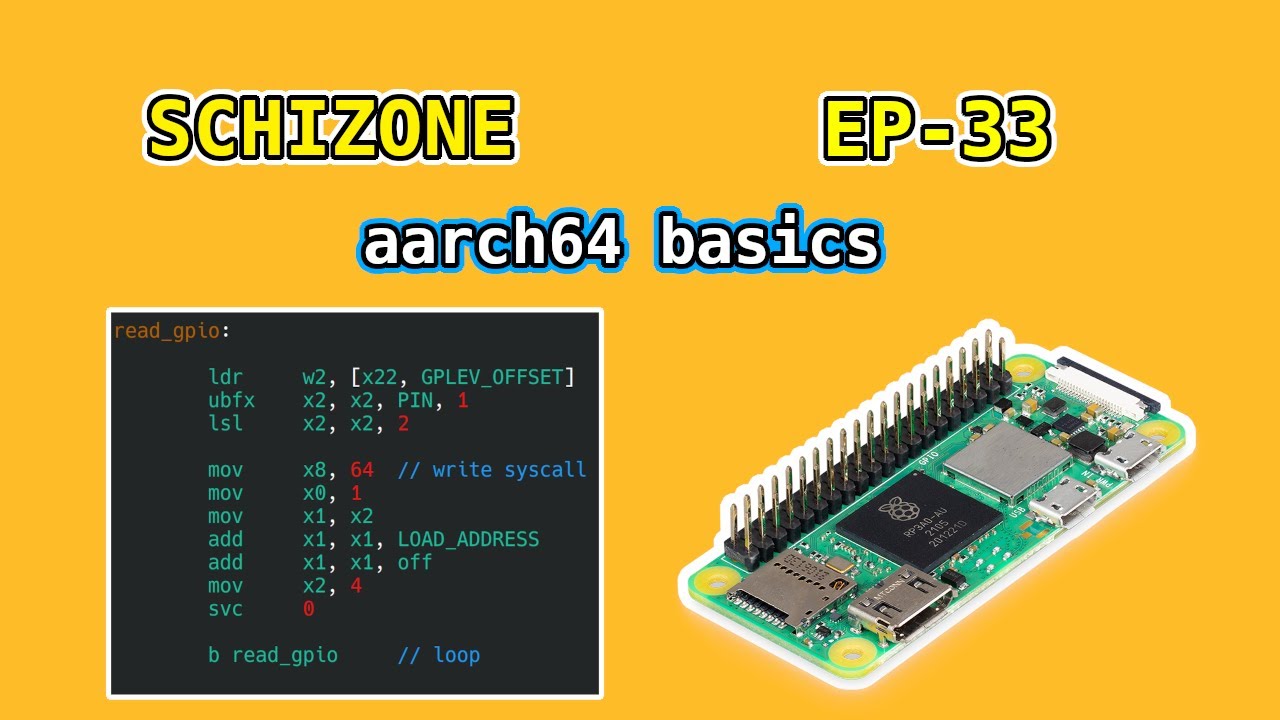
In this episode of the Skidstone series, the creator introduces a new focus on ARM64 assembly language using the Raspberry Pi Zero as the primary hardware platform. The choice of the Pi Zero is driven by its low cost, energy efficiency, and ease of interfacing with real-world peripherals compared to x86 systems which often require complex USB drivers for similar tasks. Additionally, the creator highlights the convenience of SSH access on Wi-Fi-enabled devices like the Pi, allowing developers to write and run code remotely without needing a local monitor or keyboard setup. While acknowledging that other Raspberry Pi models can be used with minor adjustments to address offsets, this specific tutorial is designed around the constraints and capabilities of the ARM architecture to demonstrate fundamental concepts in assembly programming.
The technical discussion begins by contrasting the GNU Assembler (GAS) required for ARM64 against NASM, which was previously used for x86 architectures. A significant hurdle identified is that GAS generates object files containing extensive metadata like symbol tables and literal pools rather than flat binaries, necessitating a custom bash script to extract only the executable code needed for running position-independent programs. The tutorial also delves into the specifics of interacting with GPIO pins through Linux device files, explaining how registers map directly to memory locations where developers can read pin states or write values to control outputs like LEDs and inputs such as switches.
To illustrate these concepts practically, three distinct examples are presented: a minimal infinite loop executable consisting solely of an ELF header and a branch instruction that jumps back onto itself; a program that configures GPIO 19 as an output to blink an LED by setting bits in specific function select registers using GP set and clear operations; and finally, a reading example that utilizes the UBFX (unsigned bitfield extract) instruction to isolate individual pin states from a 32-bit register. The final demonstration showcases how this setup can read digital input from a simple copper switch connected to power, printing "on" or "off" based on whether current is flowing through the circuit, thereby proving that assembly code can effectively control physical hardware in real-time environments.
Read the full video transcript
Hey guys, welcome back. Skidstone series
back by popular request. Not sure how
any of you can stomach these miserable
videos, but alas, here we are with a new
branch. Actually, billions of new
branches. That's a pun, because we're
talking about ARM today, AR 64. And for
the next coming videos, it'll all be ARM
64, I anticipate. And uh what we're
going to do in these videos, well in
this video particularly, we're talk
about a minimal executable like we did a
few years ago with the x86 platform. Um
we'll talk about the basics of this ISA.
Go into the platform that I'm choosing
for this and why I chose it and then do
some basic read and write operations to
GPIO pins. I have a Pi here. We'll talk
about that how that works. So without
further ado, yes, I did choose to use
this uh Pi Zero. Um, and the reason why
is a couple things. One, it is for what
it is, it's extremely cheap. It's not,
you know, nothing. It I think it runs
you like $15 give or take for a Linux
capable, small, low power device that
you can interact with the real world
with. Um, and that's really the main
thing is that if you're running like if
I wanted to use x86 to interface with
real life stuff, um, I would have to get
some kind of a USB driver working that,
you know, we could
somehow inter interface with. Uh, it's
not trivial, that's for sure. With this,
it's basically trivial. You have a a
device you can write to like a file. Um,
and you can set pin values high and low
very easily. So, this is kind of the I
would say the epitome of modern
computing and um it's I said it's it's
ubiquitous. It's popular, capable. Um
there's plenty of support online you can
find for these things. And
um if you're lucky, some of these PI
variants are actually, you know, put in
a box with a sticker on it that says
made in UK. I'm not sure how true that
actually is. It's probably just maybe
one solder operation and a sticker that
goes on there. Anyway, it's nice to see
some western uh manufacturing and I
particularly like these uh W versions of
the devices just
because you can SSH in. Um you don't
have to have a monitor. You can plug
this thing in anywhere in your house as
long as you're on the Wi-Fi network. You
can just get in. So I can plug this in
far away and uh still write and run code
on it. So that's pretty nice. Um so
yeah, that's kind of why we're doing
this. I think whatever I'm showing you
here in this video is either one for one
replaceable with any other PI variant. I
think the Pi 4 is just a drop in
substitution for what we're doing here
today. And others if um anything it's
just going to be a matter of changing
some address offsets which is not very
difficult to do. So um don't be turned
off by this
particular device if that's not what you
want to use. There's plenty of other
options.
So, just some basic differences from
x86. Um, you might think that the ISA is
different, the actual instructions, but
really they're they're not. And in fact,
I would say it's basically exactly the
same. Um, yeah, the pneumonics may
change. Yeah, the which inputs which,
you know, you put in there, parameters
for the, you know, op code, they might
change, sure, but the core syntax is all
the same. It's the same kind of idea.
Yeah, you have load instructions, store
instructions where it's just move, but
it's the same concept. It's not very
difficult to do. And in reality,
remember we in x86, we only had like
maybe 20 instructions that we were using
for
everything, not counting the floating
point ones. And so this is the same
thing. You're going to use maybe 15 20
instructions for 99% of all
your computing needs. So basically same
instructions. Um only the biggest
problem is that we can't use NASM. NASAM
is what we use for x86 and it uh only
works with that architecture. Um I I'm
not sure if there's another one you
could use instead, but I've chosen just
to use the the GNU assembler gas um for
what we're doing here today, which is a
really big problem for a couple reasons.
Talk about that in a few minutes.
Um, one cool thing you can do is, you
know, for the skits x86, I'd often use
my phone when I'm traveling to like
program stuff using Termox and, you
know, trying to do stuff. Obviously, I
can't run the code um on my phone
because my phone is an ARM processor,
but you can actually run this code on
your phone. The biggest thing is is
there's no GPIO pin, so you can't like
turn on LEDs and stuff, but you can
still run code and see if it if it
actually runs. So that's cool. Um, also
what's nice is there's a fixed
instruction length. That's one very cool
thing. Everything is four bytes. So when
you look at the disassembly, everything
is just eight characters long. It's very
very easy to track. Hey, this is one
instruction, that's one instruction,
etc. You can kind of very easily look
through. Very nice. And also, in my
opinion, I'm not very experienced in
this stuff, but I would say it probably
will outlive uh x86, so there's some
future proofing there as
well. Okay, so into the main bulk of
this uh episode here. So, if you recall
in our very first video on x86, we
talked about a minimal executable and we
wrote this basic elf header that we
could use and extend upon to basically
tell the
uh OS how to load our program into
memory and start executing it. That's
kind of what it's for. And on the left,
you have what we did in the beginning.
On the right, you have what we're doing
now with AR 64. So, how is it different?
Well, the biggest difference you'll see
is basically the tool chain is
different. And so all of the basic
like I don't know pneumonics, whatever
you call these things like DB for
defined bite, it's just different. Now
it's bite. Of course, that's not a huge
shift in mindset. So not a big deal. Um
but also because we're using the GNU
assembler, you have some other things
you have to put in there. So divine
architecture, etc. And then you you're
going to be using like these EQUs
instead of these like pre-processor type
uh percent things. But again, that's
just a very minor point. Um the biggest
thing is that some of the numbers will
change. So if you look here, the load
address that we had used for x86 was
like 20,000 hex. Um it didn't really
matter what you picked. It seemed to
work with most numbers. Um, however, for
this ARM processor, I I tried I asked
one of my friends to help me and I
couldn't get it to work lower than 8,000
hex. So, that's 32 kilobytes, right? I
think. So, I guess that makes sense to
me. That's like a page or some number
for pages. I have no idea to be honest.
Um, but next is basically when we use
NASM, we were able to output a flat
binary. Uh, you know, we used
-f.bin. And so we were able to just dump
out binaries essentially um with the
load address everything was kind of
built around that and all the the
addresses in there were kind of relative
to that which is kind of nice. However
using the new assembler it basically
wants to dump everything in an object
file which is to be expected because
that's how the C runtime and stuff works
in my understanding but because of that
like it's a real convoluted mess. So
I've just taken out everything to do
with load address and stuff like that
just because um we're going to be
writing position independent code and
it's it's just a huge headache
otherwise. So no load load address in
the actual
um I guess definitions here but we will
obviously use it to load in as entry
point for the program and we're going to
set offsets for everything um relative
to that when we get to that in a few
minutes. Okay. Um then also I guess the
biggest difference that should actually
exist that makes sense is there's a a
word defined here or we call it a short
in the new assembler. Basically it's
just a a number that encodes what the
processor is. So obviously that's going
to change between x64 and ARM 64. So of
course that one is different. Besides
that not a huge difference in the elf
header I would say.
Now, more about that uh kind of
compilation type process I just
mentioned. And so here's the overall
outline of what we're going to be doing.
We're going to be using this GNU
assembler as to compile well to assemble
our assembly code into an object temp
file. Uh and then let me just show you
what what's over here on the right. So
basically that operation is this white
line.
you get this temp object file and this
basically again tries to embed our
entire binary inside an object file with
its own header because it thinks it's a
it's you know its own you know elf file
and then it it dumps in a bunch of other
like um literal pools and symbol tables
and stuff in here for no reason. So we
basically have to come up with a way to
suck out our actual executable from this
nonsensical object file and that's going
to be our binary that we're going to be
able to run. And so basically everything
you see here is basically trying to
determine how big our executable is by
looking into, you know, one of these um
bytes here, seeing how big our our thing
is, trying to understand what that
means. And then this line here basically
sucks out um our executable from the
binary and then we just uh we run it.
That's kind of the gist of this. So not
hugely complex. In the future we can
implement this in assembly. It's not a
huge thing but for the time being a
simple bash script should be acceptable.
So yeah, like I mentioned before, the
real problem is that the new assembler
expects everything to be linked
eventually with libraries and things and
running a linker and all that. And uh
because of that, most of this object
file is nonsense and we have to get rid
of it. And as part of that nonsense is
the addresses that
uh certain labels are moved to in the
literal pool are going to actually be
like in this zone here. And so a lot of
the addresses if you were just to load
them in the conventional ARM way are not
going to be valid. You're going to get a
seg fault every time because you're
going to be looking outside of your
actual executable. So, we're going to
have to write more so position
independent code than you would normally
have to on ARM. In my understanding, you
most of it is already position
independent. Um, but there's a little
bit of tweaks we have to do on top of
what's generally uh
required. Okay. Now, into the basics of
GPIO. Again, this is um for the PI very
specific, but of course, I'm sure it's
very similar for other architectures. if
you had something else that was Linux
capable and could run and had a a dev
GPI mem file. And that's basically how
we're going to do this. We have these
this file on the processor. So basically
if you um flash Raspberry Pi OS to an SD
card and plug it in um it it's basically
Debian and it will have a device file
like this and this basically just kind
of maps directly to the register
addresses um for file or for
GPIO type register operations. So I'll
talk about that right here. But
basically um all this data you can find
in the documentation for the
peripherals. So this is the one that
I've opened up and it seems to be
correct. If your particular architecture
that you're using is different, um just
look into whatever that is and look at
the address offsets. That's what's
really important is how far you are from
the address of the start of the device
file
basically. Um but yeah, the process is
basically we're going to open this file.
We're going to mm mapap 4096 bytes and
we're going to read and write basically
bits to that file to interact with the
GPI opens. So couple steps for this. The
first thing we have to do
is use this um GPF cell. I guess that
stands for function select for general
purpose input output pins. So, what
those do is basically, I'll get to that
in a second, but you can set different
functions for different pins.
Um, for example, input and output and
potentially others as well. Uh, then you
have three
other basic sets of um four
byte entities in this file and they are
GP set and GP clear. Those two are
things you can write to with this W.
Basically, that means you can um set if
you basically uh set a one in these
different bit locations. You can turn
GPIO pins if they're outputs on, set
them to high. And with clear, a one
would make them low. So, basically, you
can just toggle these uh pins on and off
as you need. And then this GPE, that's
like the the pin level, you can read
with this R. Um, you can read the pin
level. So, if it's a zero, it'll be low.
If it's a one, it'll be high. Very
simple. And there's a couple other
things here that we'll talk about maybe
in the future, but they're not important
for today's
video. And I should say, I do believe
you can actually read the input level on
output pins, although there's no reason
to do that. Maybe unless you're just
curious about something um that you've
already set. So, that would be one
potential use for that. Okay. So,
function select I mentioned before. Um,
basically you're setting the the purpose
of each pin. And the way it's it works
is basically each of those addresses.
So, let me go back and say um I hope
this is big
enough. Basically at this address, so
offset zero basically from the file
start location. Um, this 32 bits is GPF
cell 0. And what that means is it
basically defines the functions of GPIO
pins 0 through 9. And so basically you
can kind of take your pin um integer
divide it by 10. So let's say you're of
pin pin three, right? Pin 3 is
determined by function select three on
um GPF cell zero. So the the n here is
basically your pin number divided by 10,
no
remainder. Um, and then you can just
look here and see what which pin it
actually is. I guess yeah, three would
be here because we have zero as well.
So, and then pin 19, right? Pin 19 would
be on GPF cell one because 19 is between
10 and 19. So, that would that would be
basically where this one is, just on the
next register up, which is this one
here. So, offset four. So you have to
basically come up with some logic and
I'll talk about that in a second um to
figure out which address you should be
writing to to set the pin function for
each individual pin that you want to
interact with. But yeah uh so 000 is
input 001 is output and then whatever
these ones are they have function they
have purposes as well. Uh so that's how
that works. Pretty simple. And then yeah
you can look every one is three bits.
So, um, for example, if you were curious
about setting GPIO 9, you'd be writing
to bits 27 through 29. If you're looking
at, uh, pin 0, it's the first three
bits. That's how that works. Now, for
setting the pin state, like I mentioned
before, all you do is you grab the
register. And again, this is um, I
should say back here, there were two
kind of slots, two 32-bit slots for
setting GPIO pins. And the reason why is
because this one at offset 1 C, that one
is basically for the pin number 0
through
31 and then uh this one is from 32 to
whatever is the last one. I think 53 or
something. So basically you can modulo
your pin number by 32 and that remainder
is basically this guy. So if you wanted
to turn on pin seven, you would just
write a one
to the seventh bit of at uh you know
whatever this address
is. Okay, pretty simple. And then the
same thing goes for
the GP clear. So if you want to turn off
pin 9, you would basically go to the
ninth bit on the GP clear address, which
is over here.
and you would set the one in slot number
nine. So, not too hard there either. And
then, of course, GPE, same thing, but
you're going to be reading, not writing,
obviously, because you're looking for
the PIN value. You just check if it's a
zero or a one. Not sure why they put a
typo in the data sheet there. Kind of
embarrassing, but yeah, you just read
that PIN number. And with that out of
the way, that was what, like, oh wow,
pretty long. 17 minutes. Let's talk now
about the actual code. We won't linger
too much on the details because it's
very self-explanatory and simple, but we
will talk about what we're doing.
So, if you if you pull the latest
suppository, you'll find um a new
directory. So, not a new branch
unfortunately, but a new directory which
is uh AR64. And in there, I have another
set of directories that we're going to
populate um today just looking at the
basics of ARM assembly. And so, what do
we have in here? We have um three
examples. One is the middle executable,
a basic blank hello world, and then
example of GPIO reading. And so we'll
first talk about the minimal executable.
Um if you remember, I'll just open up
the code. Well, let me show you it's
running first so you can see how this um
functions. It it's looping forever. So
the function that we're going to be
implementing here is just an infinite
branch. So it's four bytes. And which
four bytes are they? Um we can check uh
the
binary basically these are the four
bytes.
It's
so all of this is the elf header and
then these are this four bytes is the
infinite loop instruction. And so we can
talk about how that works. Um that's a
branch instruction. So it's a branch
offset zero. That's one difference
between x86 and ARM 64 is that um the
program counter instruction counter
whatever it in x86 it pointed to the
next instruction
in ARM 64 it points to the current
instruction and so if you look this is
the encoding for an infinite branch it's
00001 that's that's a one in hex and
then 01 and then everything else is zero
So this immediate encodes where I'm
jumping to. Um then this is just 0 1 0
0. And so your encoding is literally 01
04 0 0 0 or something whatever that
happens to be. So if you go back. Yeah.
Uh so 1 4 and then a bunch of
zeros. What did I say? Did I say 01? No.
Sorry. It's just it's just one 4
000000. I'm nuts. So yeah, that's how
that kind of encodes. Now let's look at
how that actually looks in the
um the assembly file. So before I
mentioned things we've changed basically
we've changed a couple things cuz the
assembler is different but also this
short is different now obviously because
we're a different architecture. And uh
here is our infinite loop. It's just
branch B is for branch dot is for here
branch here over and over again. And if
you're curious, you could toggle on
this. This is SIS exit. This is probably
a more appropriate middle executable
that just returns a value um 33, but uh
who cares about that? So if you look,
yeah, this was 124 bytes. That matches
up with minimum executable, I believe,
from x64, which is to be expected
because you have I think it's uh 120
bytes of the ELF and program header
combined. I think it's like 64 healther
56 program header and then four bytes
for that one instruction. And I
mentioned before all instructions in
this particular mode are four bytes. Um
I'm not sure they have thumb mode on
this. You can check but that would be
shorter potentially. Okay, that's the
first example. Very simple. You can see
if you run it, it just uh loops forever.
So that's kind of boring. Onto the next
example. Example B. This is blank. And
for this one, I will run it and I will
turn on
my camera so you can actually see what
I've got here in front of me.
Um, yep. So, I've I've got a Pi Zero
here. I got this ribbon cable that
basically just grabs the pins and
expands them here so you can see what
we're doing. Um, and and basically,
yeah, I've just got a LED running to
GPIO 19. Sorry, it's so blurry. And, uh,
if I run the code
now, let me
just, you can see it's blinking. So, uh,
not very interesting to look at. I'll
turn off the camera really quick and
we'll get back to the the program. And
so, yeah, how is this working? Let's
take a look in the
code. So, same old header. Nothing of
interest here. Potentially there's one
difference and that is I'm loading in.
So remember for x86 we had like
um a binary and then we had a bunch of
like space for the heap and other data
that we didn't want to actually store in
the binary itself. But when the program
loads you want to have space for it. And
so basically when the OS loads this
program into memory, it loads in a you
know code which we have of size code
size but then also it loads in a bunch
of zeros um after the fact. And why is
that? Well, that's because we have to m
map open and m map this 4 kilobyt of the
device for the GPI openings. And so
basically at the end of this file I've
determined um that amount of space that
we need and just uh mapped it there. So
we can access it uh at that that address
basically. So how does this work a bit
more involved? Let's talk about this
more thoroughly. So I mentioned that
we're using pin 19 and so I've defined
the pin at 19 and then I have some
examples of well not examples but some
computations of the offsets in the
device file for the addresses um of
different things. So the function select
register the GP set and should be clear
as well as the just the value for the
bit offset. So what are these things? So
remember um there were multiple GPF cell
registers or we'll call them uh like
four byte locations in that file. And so
they
were at these different addresses. And
so if if you look like some of them
were, you know, they're multiples of
four bytes offset from the start address
of the file. And so the first thing
we're doing is basically determining for
pin 19, we're actually on, you know, the
four byt offset from a start address. If
we're on pin 23, we'd be on the 8 byt
offset. If we're on pin 4, we'd be on
the zero byt offset. That's what this
one's doing. GP set and GP clear, the
same thing. Just calculating the
location of
the respective GP set and GP
clear locations. And then the bit offset
is basically when we were looking at
turning on and off this guy, which pin
are we actually referring to? So pin 19
is just the 19th pin. And
so
or no, sorry, that's too easy. That's
just a matter of just taking this modulo
32. This is actually looking at the the
the function select offset here. So if
you look um each of these was three bits
and so we just shift basically by that
many bits. So that's pretty simple. Um
and then the first step is just to open
the device file. So we have the file
name defined at some location and then
there's uh you remember there's some
inputs for that SIS call that you have
to put in. And so 56 is the file is
sorry it's the SIS call number.
Um and uh you can open it with certain
flags and directory reliveness and um
run the sys call and that returns the
file descriptor that you're going to be
referring to later on. But uh I guess
the main difference here from what you
would maybe expect in ARM assembly is
this nonsense for x1. This is going to
basically point to the address in your
binary or when your program is loaded
into memory where where the address of
the file name actually is. And so I've
called it GPIOM path. And I think
normally you would just load in um the
value at this address, which you can do
just fine if you use the new assembler
because that's going to be a literal
pool location. You can do that no
problem. Um, however, when you're
looking at this kind of stuff using, you
know, and and sucking out the executable
from
these object file, you can't do that
anymore because the address is now
wrong. So, we have to basically
reconstruct that memory location from
what we do know. So, we do know it's
offset in the the binary and we do know
it's offset
um when it's loaded into memory. And so
we can basically add those two things
together. This is just going to be a
constant. We def make this at the top of
the file. We've you know defined this
here. And so that's just going to be
hard-coded value in the program. Um and
uh so this is basically a position
dependent load instruction. And we have
to do that because the boomers don't
want us to have any fun. Then we have mm
map. So then again this takes that file
descriptor and it um turns it into a
chunk of memory that we can interact
with. So it maps a part of our binary of
our you know load into memory chunk to
the actual device file and uh that's 222
for the sys call number and then you're
just plugging in various things
including the length of that which again
is 4 kilobyt and again we have to load
in the um memory location that we're
wanting to use as the the map location
again with that same weird position
independent LDR.
are at that point x0 comes out of that
and that points to our chunk of memory
at the very bottom of this file that now
this is
basically
this. So we have a chunk of memory now
that looks just like this and we can
interact with it just like this and so
we can write to bits anywhere here as
long as we know the offset from the
start of that
mapping.
So what do we
do? So first thing we do is we have to
like I mentioned before set the output
of set this the function of this pin to
be an output. And so how does that work?
Well again we are going to
be grabbing the offset location of that
particular pin. And so uh again we
calculated that beforehand. We have that
uh equation here that determines the
offset for the function select. And
we're just going to snag the four byte
quantity in there that gets dropped here
in W2. And that's basically the current
functions of pins, whatever. I guess it
would be 10 through 19 or whatever are
now in W2. W2 is the low 32 bits of the
64-bit X2 register on ARM. And basically
what we do here is we just
um clear out whatever is in there.
or it so it's just one. We set those
three bits, whatever they were before,
who cares? Now they're 001, which is
output. And then we drop that back in
the same spot where it was. And
basically, these five lines have now set
pin 19 to be an output pin. Then what I
do is I just set a
uh set a delay um that we can use later.
that's going to be in
um X4. We can grab that whenever we need
to. And then um determine our pin. Our
pin location is just uh pin 19. This
should probably be modulo. Thinking
about this now, modulo
32, but that's fine. Um and then here's
our blink loop. And so all we're doing
is we're setting that pin to be one. So
you can see W2 basically
is the old pin states with now a one at
uh the correct
location. And all we're doing is as you
can see here we're just putting that
that pin state in X1 which is the
location of the GP set. You can see
here. And then we just have a delay. And
that delay is whatever this number is
for 400
million times. So we're just going to
loop through that 400 million time. This
is like the the decrement jump nonzero
loops that we would have in x86 that
just loop with a subtraction of one
every time. And then one thing that you
have to remember in ARM is that there's
a subtraction and then there's a
subtraction s and same thing with
addition addition s this basically just
sets like your control flags and so you
can use that at that point to determine
how long your loop lasts. Without this s
it'll just loop forever basically. So
yeah, basically you you set the the 19th
bit on this location to be one, then you
wait some time, then you clear it in the
same exact way, just to a different
register location, and then you wait
again, and then jump back to the top.
And so when we run this, it just loops
forever, blinking on and off.
like that. Okay. The next thing I want
to talk about is the next
example which is
example
C. So, um, this one is a bit different.
Let's talk about how this
one works before we actually show it.
And so, again, header is exactly the
same. And I would say this is actually
less work because you don't have to
write to two different locations. We're
just reading from one and so it becomes
inherently easier and also we only care
about doing it at, you know, obviously
one location. And so all this is the
same. We open the same file and map it
to the same spot. And now all we're
doing is we're going to be setting it to
be an input pin. And so it's the same
thing as before, but even easier because
all we have to do is clear those three
bits. So whatever they were before, they
could be 111. We just have to end that
with the three zeros in the right spot,
which is what this is. And now it's set
to zero. So that's what that does. Now
we have a loop that it's going to loop
forever and just evaluate the pin state
that we picked. And we've picked again,
I think pin
19. So
yeah, same
pin. So all that happens now
is we load
the pin states at that location. So
there's going to be 32 pin states at W2
now. And one of those pin states is the
one that we care about. Then there's
this instruction here, UBFX. What does
it stand for? We can check. I actually
have no idea what it stands for. Let's
check. You can always look at this. Um
I'll put this in the description.
um unsigned bitfield
extract, which is exactly what we're
doing. We're basically extracting one of
the pin levels. And so from W2, which is
also X2, I'm just taking
out one pin, one bit of information at
this pin bit. So pin is 19. And so I'm
looking at the 19th bit, which is
exactly what we did when we talked about
how this thing works.
Again, you're just looking exactly at
the pin number. And so, pin 7 is at
offset 7. Pin 12, offset 12. And so,
again, we just are extracting the pin
number, just one pin. And then, I just
being a little bit clever here. I didn't
want to have to do compares and stuff. I
have to talk about how that works. So,
this is just basically kind of a I guess
it's like a branchless evaluation of
what we're doing. So, I'm taking the pin
level. So, it's either going to be zero
or one.
And then I'm multiplying it by four. So
now it's either going to be zero or
four. And what that means is that now I
can have these two strings in memory off
and on. They're both four bytes long. I
put an extra space in on, so it's four
bytes. And now I can
basically print out one or the other.
And remember off is that offset off and
on is that address off + four. And so I
can basically
use this value in x2 now which is either
zero or four to point to either off or
on the strings to print. That's what
we're doing here. So just a right cyst
call. Um that's number 64 to the
standard out descriptor. And I'm just
now loading in the address off or on
based off what the result was. And then
I'm uh printing it out and jumping back
to the top. And so yeah, that's how that
works. And we can run this. And I
probably should have made the input a
little bit smaller. Let me do that
really quick so you guys can see things
in real
time. Apologies for
this. So if I run this
code and say it's off. Well, that's just
because the LED is off. I can also plug
in this guy here. Let me maybe even zoom
out a bit.
I've got this. Whenever I can, I try to
make things from scratch, obviously. So,
this is a little switch basically. Um,
it's got some copper contacts in there
just to
connect electrons or whatever. I don't
know, dude. Um, but yeah, we can connect
this
to power. And whenever I separate these
two copper contacts, it uh it says off
and I touch them, it says on, off, on,
off, on, off, on.
Right. So yeah, I mean this is how uh it
works. So we can successfully read GPIO
states and uh yeah, so that's basic
input output with GPIO using the device
GPIO MEM on um Raspberry Pi in
particular, but it won't be very much
different on other variants of that or
knockoffs I don't think. And so yeah, I
mean this opens a lot of possibilities
because now we can interact with sensors
with outside peripherals, you know,
servos, lights, um, things like that,
motors. So we can actually control
things in the real world from assembly
on a device, which normally wouldn't be
possible, especially one that you can
just SSH into from anywhere in the
world. And I will also mention really
quick that Raspberry Pi has a um RPI
connect like program that lets you
literally like VPN in anywhere in the
world to your device as long as there's
a connection on the network. And so that
makes it extremely powerful to do
something like this because you can
access it from anywhere that you would
want. With that out of the way, thanks
for watching. Had some fun. I have some
big plans for this so we'll see where
this goes. Anyway, thanks for watching.